Eureka AIR delivers breakthrough ideas for toughest innovation challenges, trusted by R&D personnel around the world.

On-Vehicle Road Configuration Identifying Device

Active Publication Date: 2007-11-15
ALPINE ELECTRONICS INC
View PDF12 Cites 24 Cited by
  • Summary
  • Abstract
  • Description
  • Claims
  • Application Information

AI Technical Summary

Benefits of technology

[0006]Therefore, it is an object of the present invention to identify the road configuration around the user's own vehicle more accurately.

Problems solved by technology

However, this technology has a problem that it cannot identify the road configuration behind the user's vehicle properly if the vehicle's movement is inconsistent with the road configuration, such as when changing a traveling lane or entering a facility off the road.

Method used


Image

  • On-Vehicle Road Configuration Identifying Device
  • On-Vehicle Road Configuration Identifying Device
  • On-Vehicle Road Configuration Identifying Device

Examples


Embodiment Construction

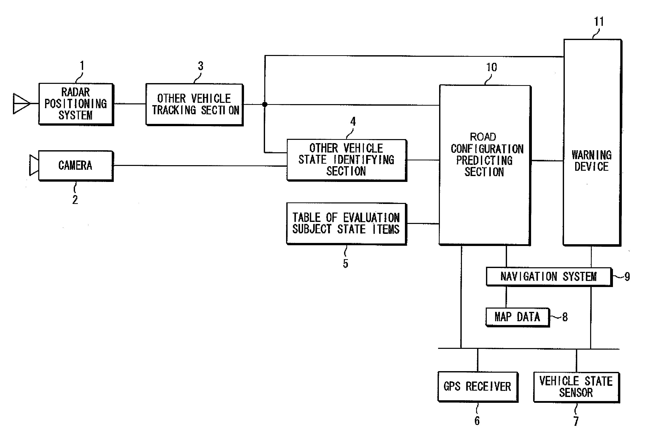
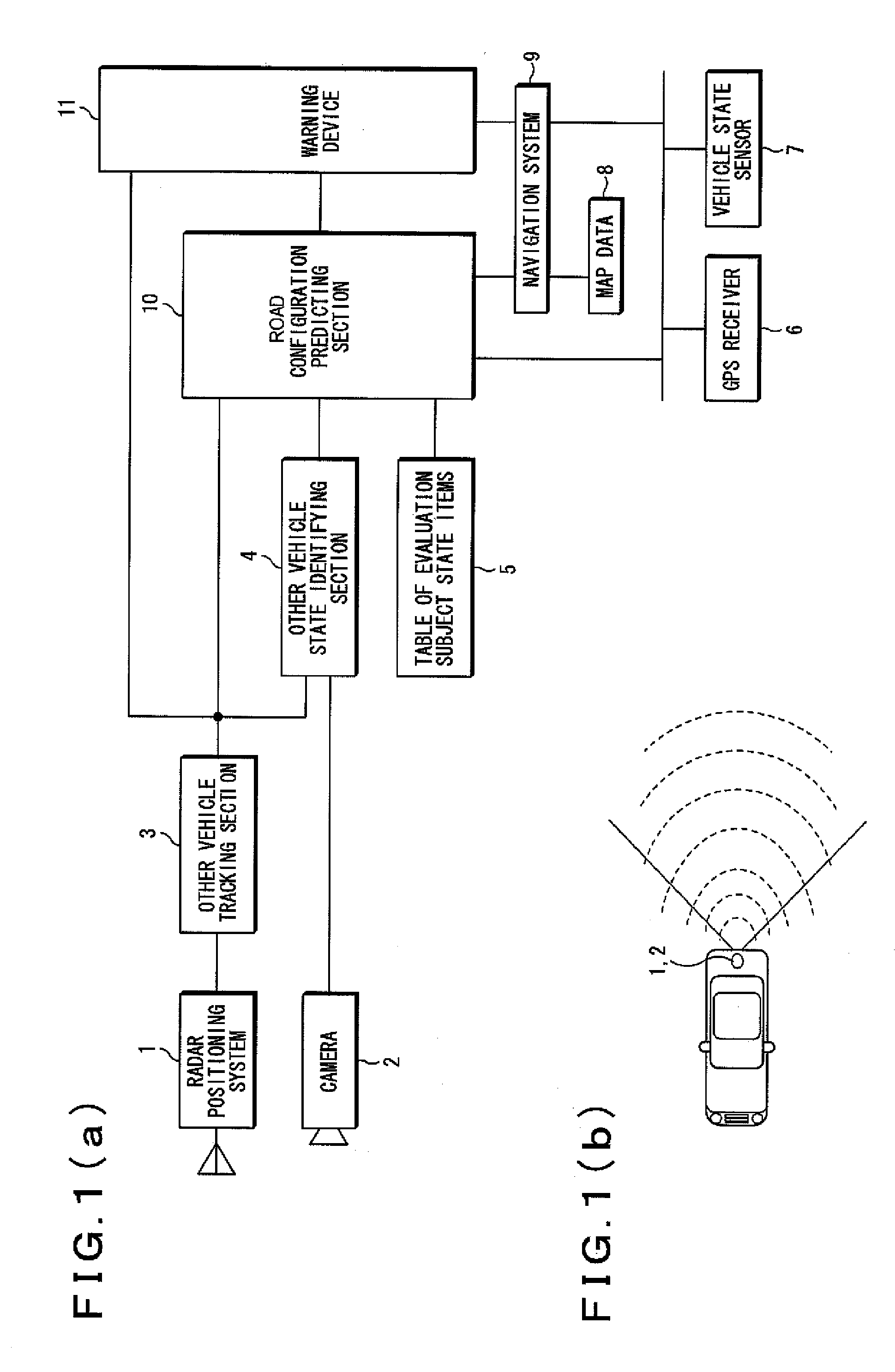
[0023]FIG. 1(a) shows the configuration of an on-vehicle system according to one embodiment.

[0024]The on-vehicle system is a device mounted on a vehicle, and includes a radar positioning system 1, a camera 2, an other vehicle tracking section 3, an other vehicle state identifying section 4, a table of evaluation subject state items 5, a GPS receiver 6, a vehicle state sensor 7, map data 8, a navigation system 9, a road configuration predicting section 10, and a warning device 11 as shown in the drawing. Here, the vehicle state sensor 7 is a collection of sensors that detects various states of the user's vehicle, such as a vehicle velocity sensor that detects the velocity of the vehicle, a gyro sensor that detects the angular velocity of the vehicle, and a sensor that detects the operation state of the direction indicator of the vehicle.

[0025]As shown in FIG. 1(b), the radar positioning system 1 is positioned at the rear of the vehicle, performs scanning for detecting the positions a...


PUM


Abstract

A road configuration identifying device properly identifies the road configuration around a user's vehicle. A reliability level indicating whether the traveling paths of other vehicles in an area behind the user's vehicle which are detected by a radar positioning system, which are obtained by tracking other vehicles using an other vehicle tracking section, and the traveling path of the user's vehicle are traveling paths along the same road configuration is calculated by using the velocity v, acceleration dv, angular velocity dθ, and the operation state of a direction indicator or the like of each vehicle. Then, the road configuration indicated by traveling paths having a high reliability level is predicted as the road configuration in the area behind the user's vehicle. A warning device evaluates the possibility of other vehicles colliding with the user's vehicle based on the road configuration of the area behind the user's vehicle predicted by the road configuration predicting section and the behavior of other vehicles tracked by the other vehicle tracking section, and warns of the possibility of collision if such another vehicle is present.

Description

RELATED APPLICATION[0001]The present application claims priority to Japanese Patent Application Number 2006-134721, filed May 15, 2006, the entirety of which is hereby incorporated by reference.BACKGROUND OF THE INVENTION[0002]1. Field of the Invention[0003]The present invention relates to technology for identifying the road configuration around a user's own vehicle.[0004]2. Description of the Related Art[0005]As an example of technology for identifying the road configuration around a user's vehicle, there is known a system for identifying the road configuration behind a user's vehicle based on the traveling path of the vehicle (Japanese Patent Laid-Open No. 6-258438 publication, for example). However, this technology has a problem that it cannot identify the road configuration behind the user's vehicle properly if the vehicle's movement is inconsistent with the road configuration, such as when changing a traveling lane or entering a facility off the road.SUMMARY OF THE INVENTION[00...

Claims


Application Information

Patent Timeline
IPC IPC(8): G01C21/00G06F17/10G01S13/931
CPCG01C21/26G01S7/41G01S2013/9378G01S2013/9353G01S13/931G01S2013/93272G01S2013/932
Inventor MUNAKATA, KOHSUKE
Owner ALPINE ELECTRONICS INC
Why Eureka
Eureka Blog
Learn More