
Trainline support bracket

Active Publication Date: 2007-11-22
EOC RAILCAR SOLUTIONS
View PDF8 Cites 12 Cited by
  • Summary
  • Abstract
  • Description
  • Claims
  • Application Information

AI Technical Summary

Problems solved by technology

Type 1a above may not adequately compensate for relative motion on some cars, may require wide variety of design geometries, and its performance is sensitive to application errors.
Type 1b above is suspected to contribute to hose separations because of several degrees of freedom, undesirable forces and motions transmitted through components of the system, likely interference with car components on some cars, and sensitivity to application errors.
The high number of degrees of freedom makes performance difficult to predict.
Current designs only compensate for axial movement of the coupler, but not for rotation of the coupler relative to the car.
The rigid design may also lead to kinking of hoses between cars and to difficulty coupling hoses when the train is on a curve.
This requires forces to be transmitted through the trainline hoses to move the pipe and channel, which is relatively heavy.
The extra degrees of freedom relative to a rigid arrangement make performance difficult to predict.
This system is likely to have both the benefits and problems of other high degree of freedom systems.
It has been reported that this type of arrangement failed because the equipment would be and was torn off the coupler in the event of a bypassed coupler event, which is when a coupler on one car is misaligned with the coupler on the second car during coupling and the couplers slide alongside each other with tremendous force.

Method used


Image

  • Trainline support bracket
  • Trainline support bracket
  • Trainline support bracket

Examples


embodiment 10

Preferred Embodiment 10

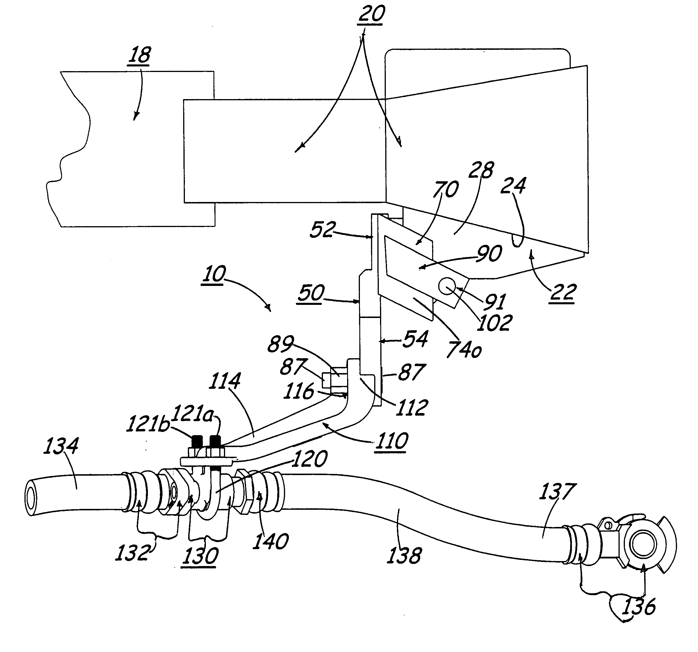
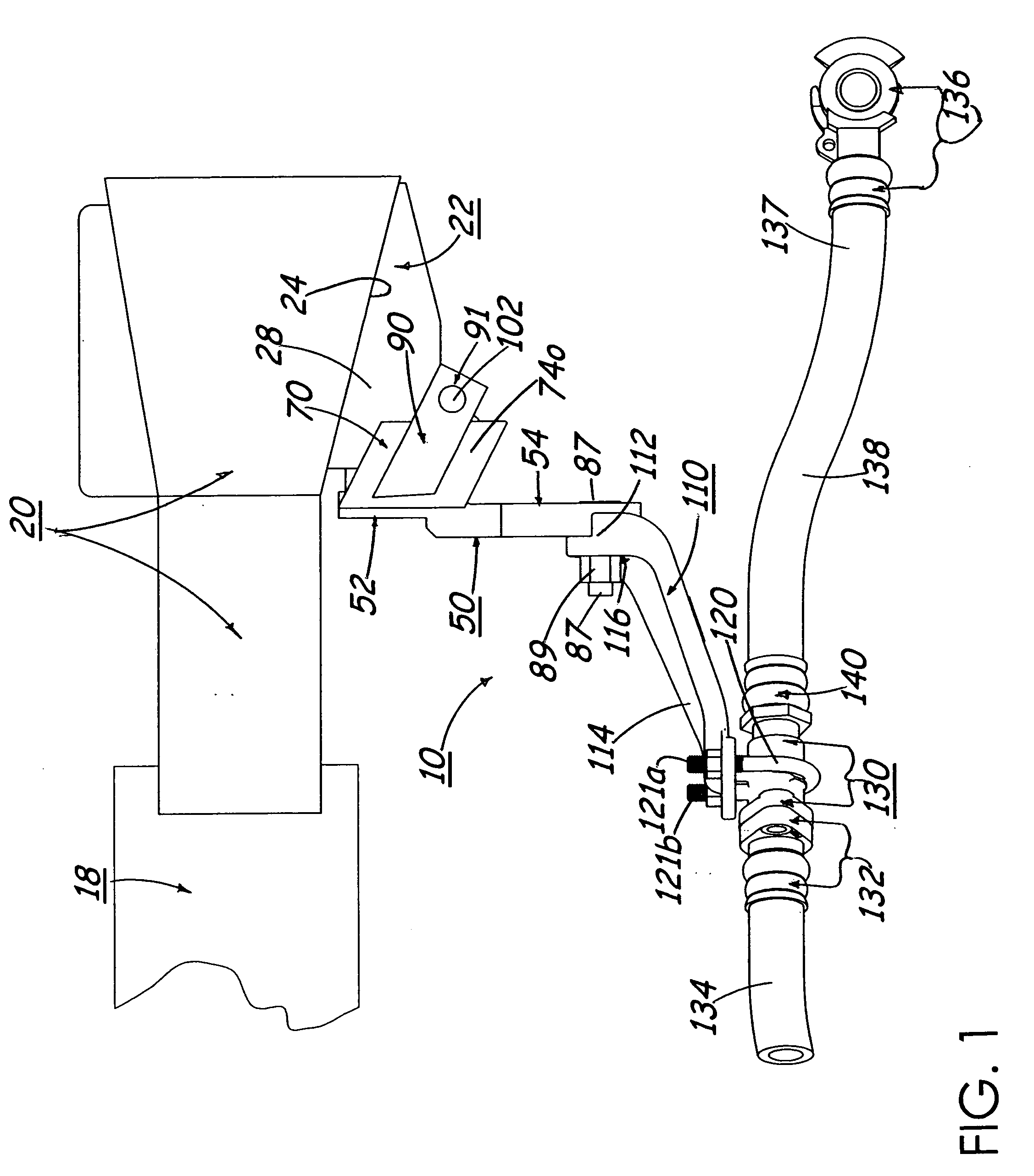
[0047]The trainline support bracket 10 and its component parts of the preferred embodiment are represented in detail by FIGS. 1 through 8 of the patent drawings. The trainline support bracket 10 is used in conjunction with a railcar yoke 18 and a railcar coupler 20 having a coupler-uncoupling mechanism housing 22 thereon for preventing the brakeline hose separation on moving railcars, as shown in FIG. 8.

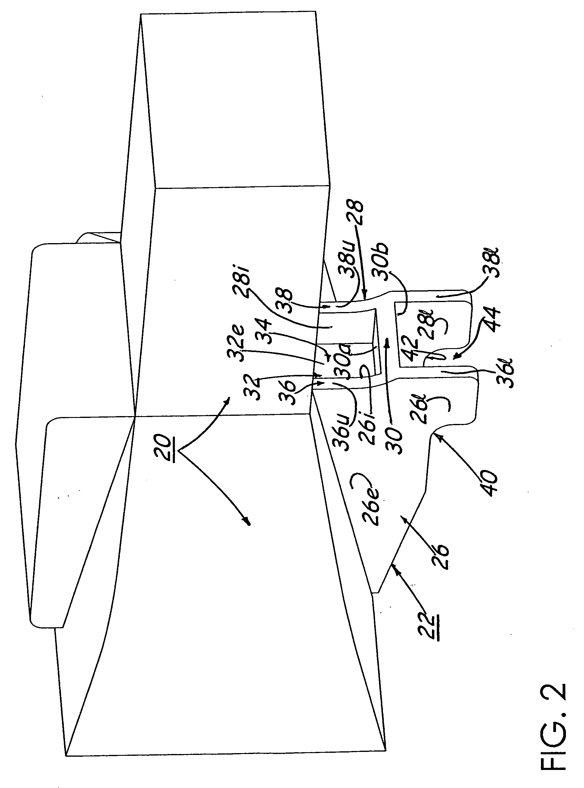
[0048]The coupler-uncoupling mechanism housing 22 extends downwardly from the railcar coupler 20 and is integrally attached to the railcar coupler 20, as depicted in FIGS. 1 and 2. The coupler-uncoupling mechanism housing 22 includes a coupler head bottom wall 24, a first side wall 26 having an exterior wall surface 26e and an interior wall surface 261, a second side wall 28 having an exterior wall surface 28e and an interior wall surface 281, an interior horizontal bottom wall 30 having an upper bottom wall surface 30a and a lower bottom wall surface 30b, and ...

first alternate embodiment 200

First Alternate Embodiment 200

[0054]The trainline support bracket 200 and its component parts of the first alternate embodiment of the present invention is represented in detail by FIG. 9 of the patent drawings. Elements illustrated in FIG. 9 which correspond to the elements described above with reference to FIGS. 1 through 8, have been designated by corresponding reference numbers increased by two hundred. The first alternate embodiment 200 is similarly constructed and operates in the same manner as the preferred embodiment 10, unless it is otherwise stated.

[0055]All aspects of the first alternate embodiment of the trainline support bracket 200 are the same as the preferred embodiment of the trainline support bracket 10 except for a U-shaped holding extension bar or member 264 having opposing contact extension blocks 265a and 265b being centrally positioned on wall surface 256 adjacent to the upper contact pad 262 of the upper connector section 252 of the main body connector 250. T...

second alternate embodiment 400

Second Alternate Embodiment 400

[0057]The trainline support bracket 400 and its component parts of the second alternate embodiment of the present invention is represented in detail by FIG. 10 of the patent drawings. Elements illustrated in FIG. 10 which correspond to the elements described above with reference to FIGS. 1 through 8 have been designated by corresponding reference numbers increased by four hundred. The second alternate embodiment 400 is similarly constructed and operates in the same manner as the preferred embodiment 10, unless it is otherwise stated.

[0058]All aspects of the second alternate embodiment of the trainline support bracket 400 are the same as the preferred embodiment of the trainline support bracket 10 except for the integration of the first end 512 of the lower connecting bracket 510 as an integral unit with the lower connector section 454 of the main body connector 450 (see FIG. 10). The trainline support bracket 400, as depicted in FIG. 10, now has an L-s...


PUM


Abstract

A trainline support bracket for connection to a railcar having a yoke and a coupler attached to the railcar and a coupler-uncoupling mechanism housing attached to the coupler having first and second side walls with first and second contoured recess members thereon, and having upper and lower compartments for attaching the trainline support bracket thereto. The trainline support bracket includes a main body connector having an upper connector section and a lower connector section. The upper connector section of the main body connector is for connecting to the coupler-uncoupling mechanism housing of the coupler. The trainline support bracket also includes a lower connecting bracket having a first end and a second end. The lower connector section of the main body connector is for detachably connecting to the first end of the lower connecting bracket; and the second end of the lower connecting bracket is for detachably connecting to a trainline fitting in order to support hose fittings, hoses and a gladhand coupling having a hose connected to the coupling.

Description

FIELD OF THE INVENTION[0001]The present invention relates to a trainline support bracket for mounting a brake system hose, pipe and fitting line, commonly known as a trainline, to a railcar. More specifically, the trainline support bracket is intended for use on “cushioned cars”.BACKGROUND OF THE INVENTION[0002]Cushioned cars are well-known in the prior art of railcars for trains. Cushioned cars may be of two types: the end of car cushioning type or the center of car cushioning type. End of car cushioning is a system whereby the couplers that connect one railcar to another are connected to spring and / or damper devices and therefore move relative to the railcars to produce a cushioning effect meant to protect the cargo in the railcars. Cars with center of car cushioning, also known as sliding sill cars, have a main structural sill that moves relative to the car body to allow travel of a spring and / or damper device.[0003]While most railcars have some degree of cushioning, “cushioned c...

Claims


Application Information

Patent Timeline
IPC IPC(8): B61G7/00
CPCB61G7/00
Inventor MCKIERNAN, KEVIN
Owner EOC RAILCAR SOLUTIONS
Learn More