
Dispensing Device, Storage Device and Method for Dispensing Powder

a technology of a storage device and a dispensing device, which is applied in the direction of inhalators, other medical devices, pharmaceutical product form changes, etc., can solve the problems of insufficient de-agglomeration of powder, inability to de-agglomerate powder, and inability to achieve optimal de-agglomeration of powder, etc., to achieve the desired spray plume characteristics and/or better de-agglomeration of powder

Active Publication Date: 2007-11-29
BOEHRINGER INGELHEIM INT GMBH
View PDF35 Cites 116 Cited by
  • Summary
  • Abstract
  • Description
  • Claims
  • Application Information

AI Technical Summary

Benefits of technology

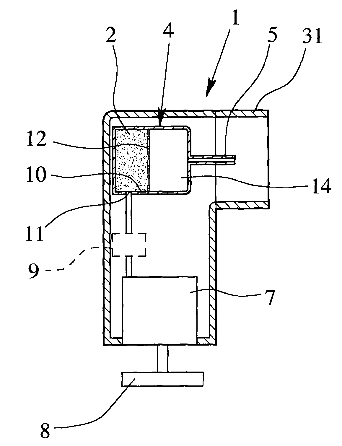
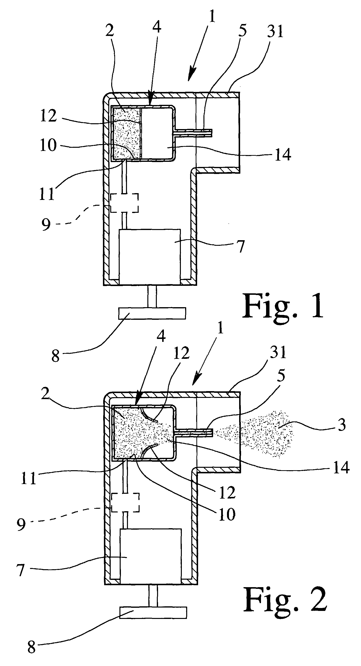
[0013] A primary object of the present invention is to provide an improved dispensing device, storage device and method for dispensing powder, in particular, wherein better de-agglomeration of the powder and / or the desired spray plume characteristics can be realized.

Problems solved by technology

The problem with passive inhalers is that the inhalable fraction, or the proportion of powder that actually enters the lungs, is largely dependant on the breathing of the patient.
In many applications, the active duct powder is mixed with a carrier, such as lactose which tends to absorb humidity from the atmosphere which makes it stick together and difficult to de-agglomerate.
However, the known device and method are not optimal for de-agglomerating the powder and for generating a slow spray plume with the desired characteristics.

Method used


Image

  • Dispensing Device, Storage Device and Method for Dispensing Powder
  • Dispensing Device, Storage Device and Method for Dispensing Powder
  • Dispensing Device, Storage Device and Method for Dispensing Powder

Examples


example 1

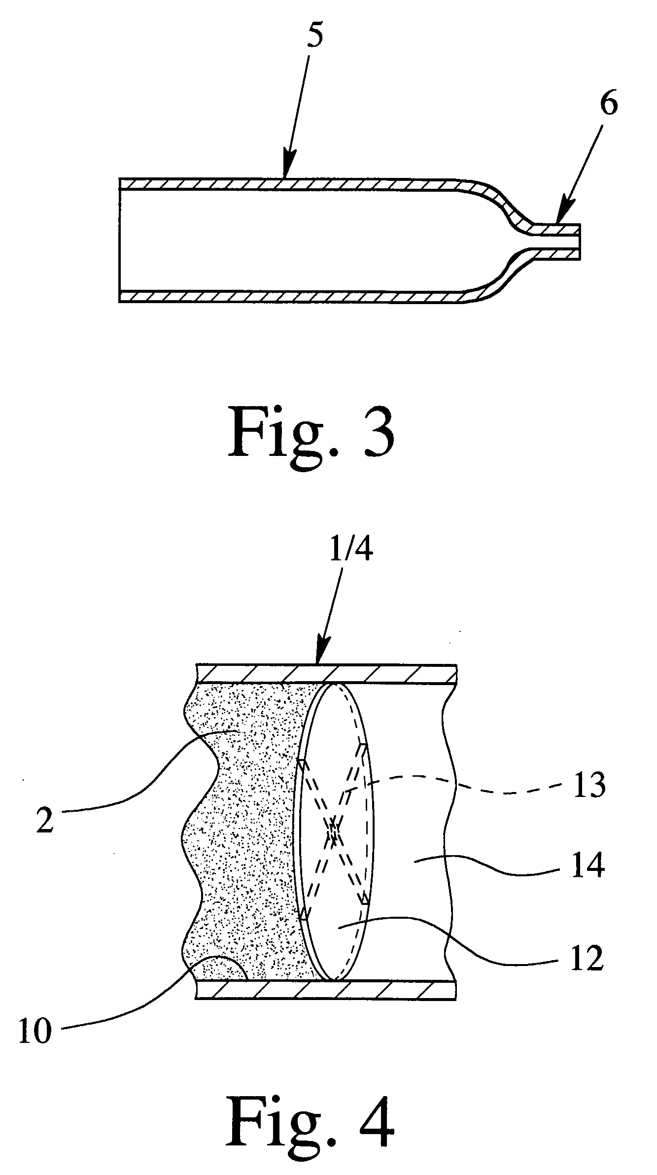
[0145] A blend of 90.0% by weight of lactose 200, of 9.7% by weight of fine lactose, and of 0.3% by weight of Tiotropium was used. The mean particle diameter of lactose 200 was about 45 μm, of fine lactose about 4 μm and of Tiotropium about 4 μm. About 5.5 mg of the blend was positioned as powder 2 in the storage and mixing chamber 10 / 14 which had a substantially cylindrical shape with a diameter of 3 mm and an axial length of 3 mm. 5 ml of compressed air was supplied via the gas inlet having an inlet orifice of 0.5 mm into the chamber 10 / 14 with a gauge pressure of about 100 kPa. The powder 2 was dispensed via duct 5 of substantially rectangular cross section having a smallest side of about 0.18 mm and a largest side of about 1.5 mm. The duct 5 divided into two duct sections 5a, 5b (in particular, as shown in FIG. 13), wherein each section had a substantially rectangular cross section with a smallest side of about 0.18 mm and the largest side of about 0.75 mm. The total length of t...

example 2

[0146] About 1.5 mg of Fenoterol with a mean particle diameter of 4 μm was positioned as powder 2 in the storage and mixing chamber 10 / 14 which had a substantially cylindrical shape with a diameter of 2 mm and an axial length of 2 mm. 5 ml of compressed air was supplied via the gas inlet having an inlet orifice of 0.5 mm into the chamber 10 / 14 with a gauge pressure of about 150 kPa. The powder 2 was dispensed via a duct 5 of substantially rectangular cross section having a smallest side of 0.075 mm and a largest side of 1.5 mm. The duct 5 was divided into two duct sections 5a, 5b (in particular, as shown in FIG. 13), wherein each section had a substantially rectangular cross section with a smallest side of about 0.075 mm and the largest side of about 0.75 mm. The total length of the channel including the sections 5a, 5b was about 8 mm. The result was that 100% of the metered mass, i.e., all of the powder 2 in chamber 10 / 14, was dispensed. Approximately 45% of both diameter mean and ...


PUM


Abstract

A dispensing device, a storage device and a method for dispensing powder in which powder is dispensed through a duct with a flat cross section to de-agglomerate the powder and to generate a spray with fine particle size. A storage chamber for the powder may be closed by a bursting element which is burst by pressurized gas for discharging the powder, the gas pressure reaching or exceeding a peak value before the bursting element bursts so that the powder is dispensed at a lower gas pressure. The powder may be forced through the duct by a gas pressure of less than 300 kPa to de-agglomerate the powder and / or to generate the spray. The storage device can have multiple storage chambers and associated ducts or nozzles, so that each dose of powder can be dispensed through a separate duct or nozzle.

Description

BACKGROUND OF THE INVENTION [0001] 1. Field of the Invention [0002] The present invention relates to a dispensing device for dispensing powder, in particular, containing or consisting of a drug, as a spray including fine powder particles, and to a storage device for such powders which has at least one, and preferably, multiple separate storage chambers, each containing a single dose of the powder to be dispensed by gas pressure. The invention also relates to a method for dispensing a spray including fine powder particles by means of gas pressure. [0003] 2. Description of Related Art [0004] Powder drugs delivered through dispensing devices, in particular, inhalers, are intended to optimally target specific sites in the pulmonary system. These sites include the nasal passages, the throat, and various locations within the lungs, such as the bronchi, bronchioles and alveolar regions. The ability to deliver drugs to a target area depends, inter alia, on the aerodynamic sizes of the parti...

Claims


Application Information

Patent Timeline
IPC IPC(8): B65D83/14A62C5/02B05B9/04
CPCA61M11/02A61M15/0028A61M15/0045A61M2202/064A61M2205/073A61M2205/8225A61M15/0051A61M15/0003A61M15/002A61M15/0031A61M15/0033A61M15/0048A61M2206/16A61M11/001A61M11/002A61J3/02
Inventor DUNNE, STEPHEN TERENCEROHRSCHNEIDER, MARCMOSER, ACHIM
Owner BOEHRINGER INGELHEIM INT GMBH
Features
  • Generate Ideas
  • Intellectual Property
  • Life Sciences
  • Materials
  • Tech Scout
  • Unparalleled Data Quality
  • Higher Quality Content
  • 60% Fewer Hallucinations
Learn More