Method, apparatus, and program for image forming capable of effectively adjusting positional deviation

a technology of positional deviation and program, applied in the field of image forming apparatus, can solve the problems of color misregistration or color misregistration problem, temperature sensor may increase the cost, undetectable increase the number of operations of positional deviation adjustment, etc., to achieve high quality, and effect of effective adjustment of positional deviation

Active Publication Date: 2007-11-29
RICOH KK
View PDF17 Cites 13 Cited by
  • Summary
  • Abstract
  • Description
  • Claims
  • Application Information

AI Technical Summary

Benefits of technology

[0033] Exemplary aspects of the present invention provide an image forming apparatus that can effectively adjust positional deviation to produce a high quality image without providing additional units.
[0034] Other exemplary aspects of the present invention provide an image forming method that can be performed in the above-described image forming apparatus to effectively perform the adjustment of the positional deviation for producing a high quality image.
[0036] In one exemplary embodiment, an image forming apparatus includes a plurality of image bearing members configured to bear respective images thereon, a transfer device configured to transfer the respective images formed on the plurality of image bearing members and include a transfer member in a form of an endless loop and configured to receive the respective images on one of a surface of the transfer member and a recording medium carried by the transfer member, an image detecting unit configured to detect the respective images conveyed on the transfer member, a paper length detecting unit configured to detect a length of a recording medium in a sheet travel direction, a counting unit configured to count the number of recording media including the recording medium conveyed to the transfer device and to change a count up value for each recording medium according to a detection result obtained by the paper length detecting unit, and a control unit configured to control an image forming timing with respect to the plurality of image bearing members based on a detection timing of the image detected by the image detecting unit and to perform a positional deviation adjustment each time a counted value obtained by the counting unit increases by a predetermined amount, so as to reduce an amount of a positional deviation of the image caused when the image is superimposed on the transfer member or on the recording medium.

Problems solved by technology

Such color image forming apparatuses may cause a color misregistration or color misregistration problem.
The above-described technique, however, has a disadvantage that a temperature sensor may increase the cost.
This can undesirably increase the number of operations of the positional deviation adjustment.
However, even though it is expected to mass-produce such image forming apparatuses for the general user, it is not preferable to increase the amount of color misregistration and the number of times to force users to wait, which may be referred to as “the number of waits” because of the positional deviation adjustment.
Unfortunately, in order to surely maintain the amount of color misregistration within its allowable range when the positional deviation adjustment is performed based on the predetermined amount of printouts, the general user has to wait the number of times that is greater than the allowable number of waits.
To perform the positional deviation adjustment with the above-described condition, however, a new configuration or structure for counting the driving period of the image writing device may be additionally required, which can cause an increase in cost.

Method used


Image

  • Method, apparatus, and program for image forming capable of effectively adjusting positional deviation
  • Method, apparatus, and program for image forming capable of effectively adjusting positional deviation
  • Method, apparatus, and program for image forming capable of effectively adjusting positional deviation

Examples


Embodiment Construction

[0081] In describing preferred embodiments illustrated in the drawings, specific terminology is employed for the sake of clarity. However, the disclosure of this patent specification is not intended to be limited to the specific terminology so selected and it is to be understood that each specific element includes all technical equivalents that operate in a similar manner.

[0082] Referring now to the drawings, wherein like reference numerals designate identical or corresponding parts throughout the several views, preferred embodiments of the present invention are described.

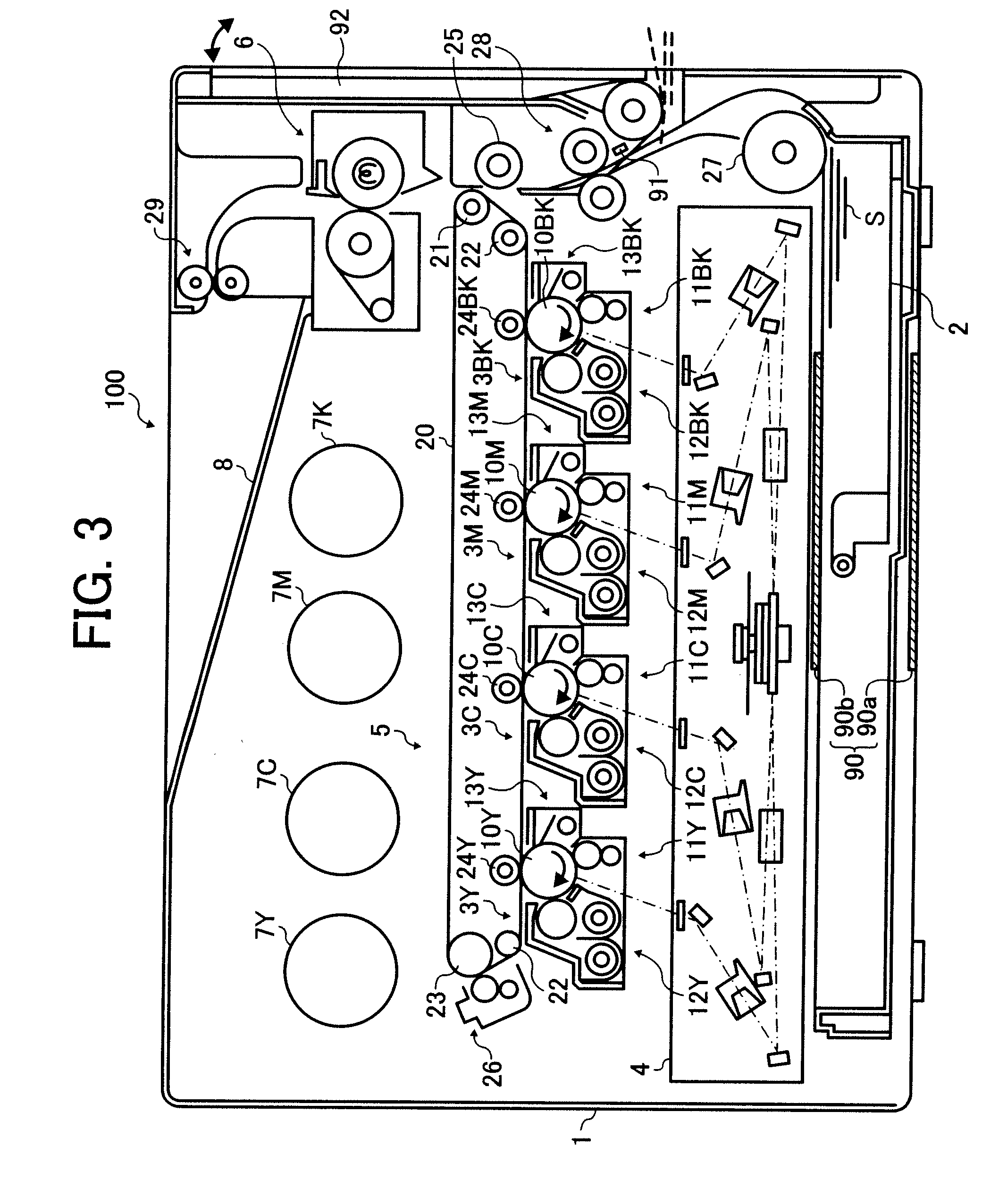
[0083] Referring to FIGS. 3 and 4, schematic structures of a printer 100 according to an exemplary embodiment of the present invention is described.

[0084]FIG. 3 shows a schematic configuration of the printer 100 according to an exemplary embodiment of the present invention.

[0085] The printer 100 of FIG. 3 includes a main body 1 and a sheet feeding cassette 2 that can be inserted into or pulled out from the main...


PUM


Abstract

An image forming apparatus, in which a program for carrying out an image forming method is provided, includes a transfer member to receive respective images formed on a plurality of image bearing members, an image detecting unit to detect the images conveyed on the transfer member, a paper length detecting unit to detect a length of a recording medium in a sheet travel direction, a counting unit to count the number of recording media and to change a count up value according to a detection result by the paper length detecting unit, and a control unit to control an image forming timing with respect to the image bearing members based on a detection timing of the image and to perform a positional deviation adjustment each time a counted value increases by a predetermined amount so as to reduce an amount of a positional deviation of the image.

Description

CROSS REFERENCE TO RELATED APPLICATIONS [0001] The present application claims priority under 35 U.S.C. § 119 to Japanese patent application no. 2006-124802, filed in the Japan Patent Office on Apr. 28, 2006, the entire contents of which are herein incorporated by reference. BACKGROUND OF THE INVENTION [0002] 1. Field of the Invention [0003] The present invention relates to an image forming apparatus, an image forming method performed in the image forming apparatus, and a program used in the image forming apparatus. More particularly, the present invention relates to an image forming apparatus that can effectively conduct color misregistration adjustment for forming a high quality image by sequentially overlaying respective single color images formed on a plurality of image bearing members to directly or indirectly transfer onto a recording medium, an image forming method used for the image forming apparatus, and a program used to perform the image forming method in the image forming...

Claims


Application Information

Patent Timeline
Patent Type & Authority Applications(United States)
IPC IPC(8): G03G15/01
CPCG03G15/0131G03G21/02G03G15/0194G03G2215/0161G03G2215/0119
Inventor EHARA, YASUHISAKOBAYASHI, KAZUHIKOEBARA, JOHHANDA, SEIICHIFUNAMOTO, NORIAKIUCHIDA, TOSHIYUKISUGIYAMA, KEISUKEAMANAI, KOUJI
Owner RICOH KK
Why Eureka
Try Eureka