

Treadmill having vibration damping function for its handlebars
- Summary
- Abstract
- Description
- Claims
- Application Information
AI Technical Summary
Benefits of technology
Problems solved by technology
Method used
Image

Examples
Embodiment Construction
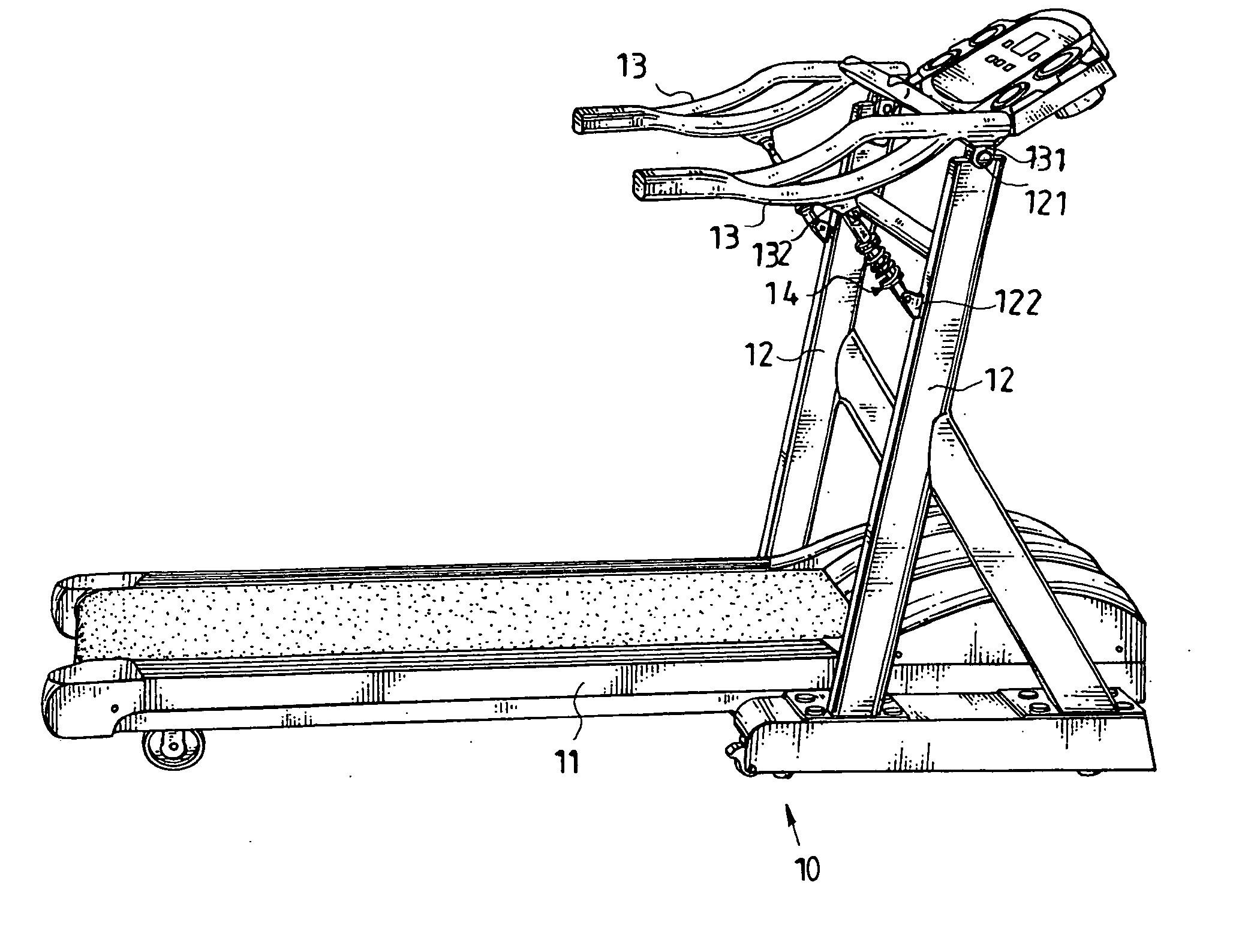
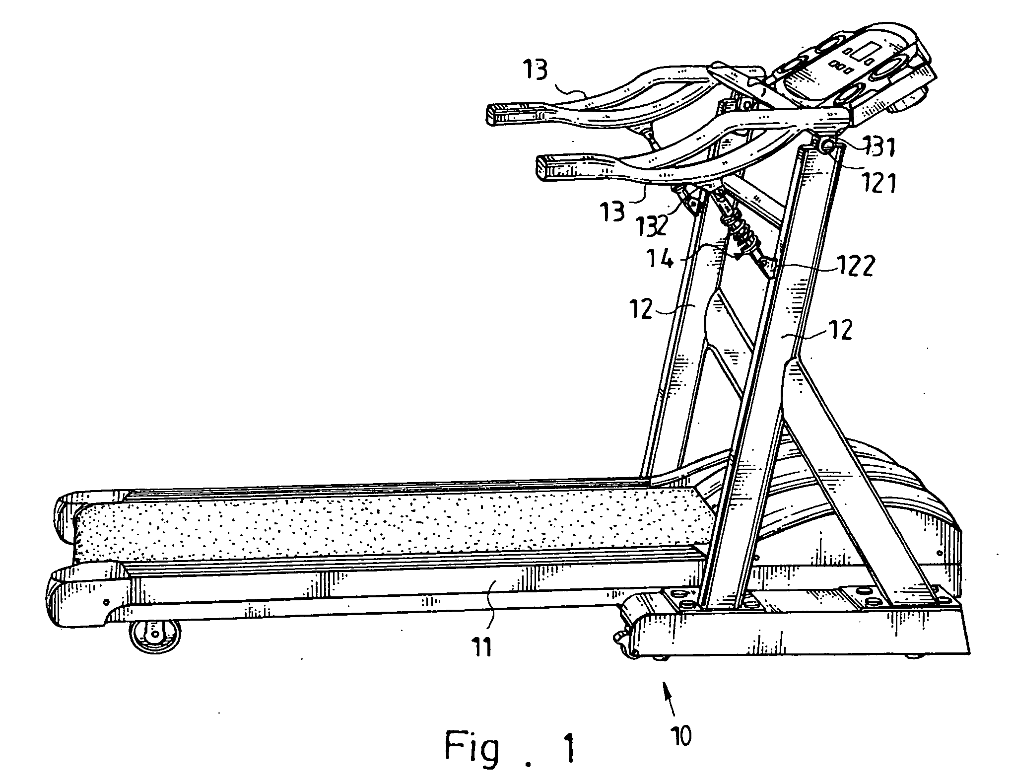
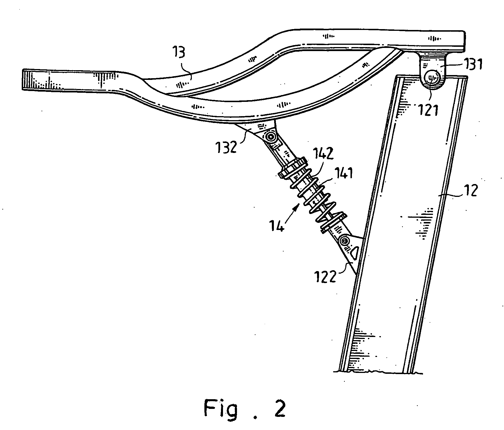
[0013] Referring to the drawings and initially to FIGS. 1 and 2, a treadmill in accordance with the preferred embodiment of the present invention comprises a tread board 11, two uprights 12 mounted on two opposite sides of the tread board 11, two handlebars 13 each pivotally mounted on a respective one of the uprights 12, and two vibration damping devices 14 each mounted between a respective one of the uprights 12 and a respective one of the handlebars 13 to provide a vibration damping effect to the respective handlebar 13.
[0014] Each of the handlebars 13 has a front side pivotally mounted on an upper end of the respective upright 12. The front side of each of the handlebars 13 is provided with a downward extending pivot ear 131 pivotally mounted on the upper end of the respective upright 12 by a pivot shaft 121. Each of the vibration damping devices 14 is mounted between a mediate portion of the respective upright 12 and a mediate portion of the respective handlebar 13. The mediat...
PUM
 Abstract
Description
Claims
Application Information