Aircraft Drive

a technology of aircraft drive and torque, applied in the direction of process and machine control, instruments, navigation instruments, etc., can solve the problems of poor machine efficiency and the provision of torque, and achieve the effect of improving performance, preventing aircraft from overbalancing, and additional precision in guiding aircra

Active Publication Date: 2007-12-06
BOREALIS TECH LTD
View PDF55 Cites 58 Cited by
  • Summary
  • Abstract
  • Description
  • Claims
  • Application Information

AI Technical Summary

Benefits of technology

[0015] The benefits of two separately driven nose wheels with speed and torque sensors include improved performance, additional precision in guiding an aircraft, and preventing an aircraft from overbalancing.

Problems solved by technology

The use of small compact electric motors inside, or in close proximity to, an aircraft wheel, for direct drive, presents a problem relating to the provision of the required amounts of torque.
The active materials of the machine will be underutilized, the machine will be far heavier than necessary, and the machine efficiency will be poor.
This presents a significant problem, because, in these cases, the wheels may be rotating faster than the motor and may accelerate the motor via the gearing system.

Method used


Image

  • Aircraft Drive
  • Aircraft Drive
  • Aircraft Drive

Examples


Embodiment Construction

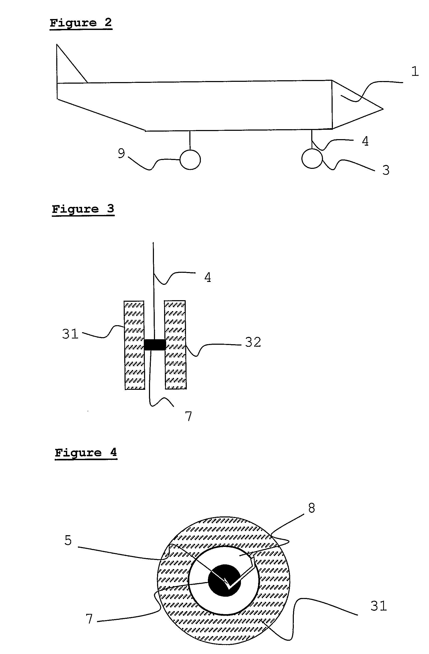
[0024] Embodiments of the present invention and their technical advantages may be better understood by referring to FIGS. 1-5.

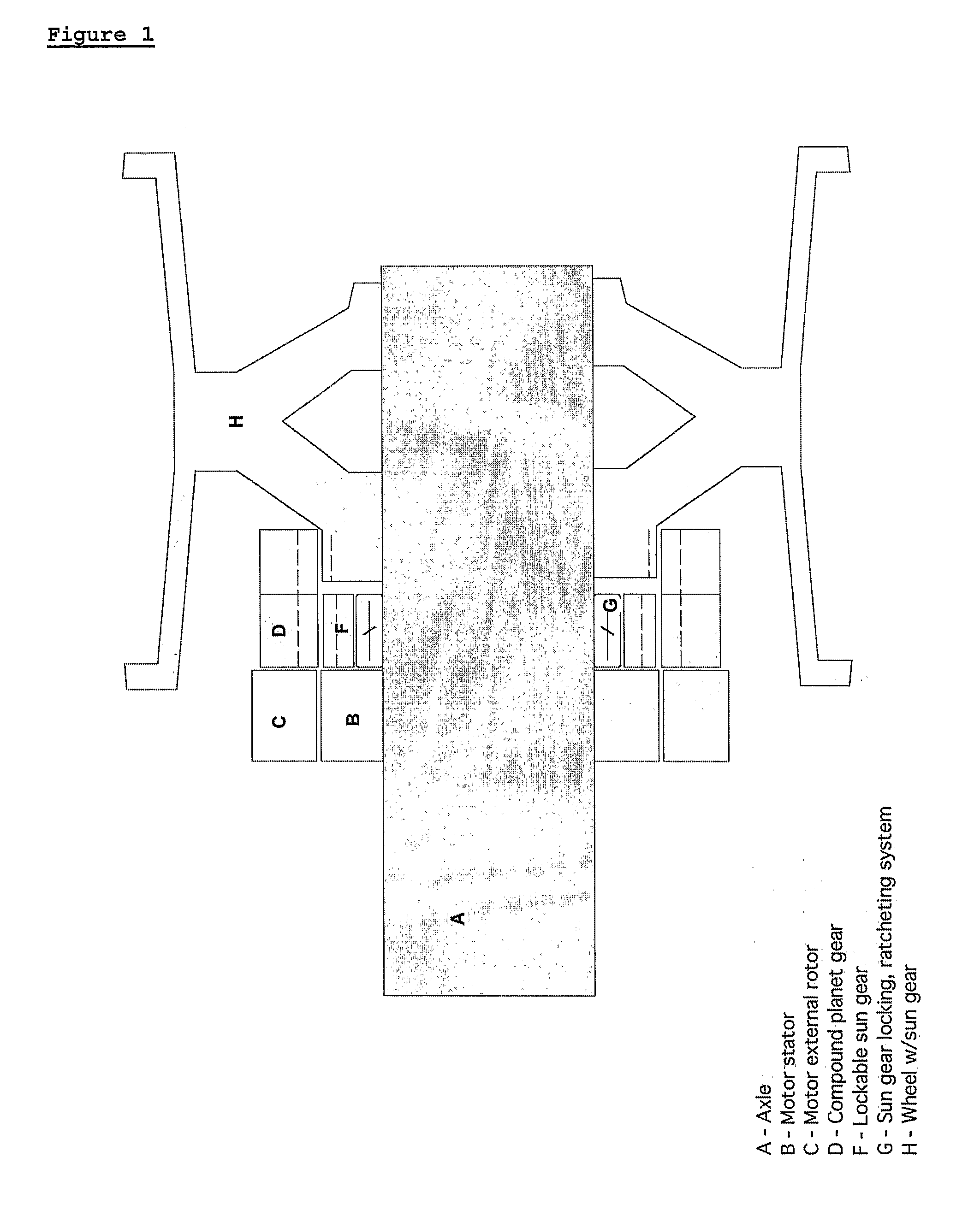
[0025] In the present invention, an aircraft nose wheel is motor driven. FIG. 1 shows one way in which a motor may be housed in the wheel and connected through a gearing system to the wheel. A motor, including stator B and rotor C, is mounted around a central axle, A, (labeled only on one side). The gearing system includes gear parts D, F, G and H, which are not an intrinsic part of the present invention. The output of rotor C is applied to the gear system, and gear H transmits the rotary power to the wheel. This example represents one way in which the motor may be housed within the wheel itself. Depending on the number of motors and their operating ranges, gearing may or may not be required.

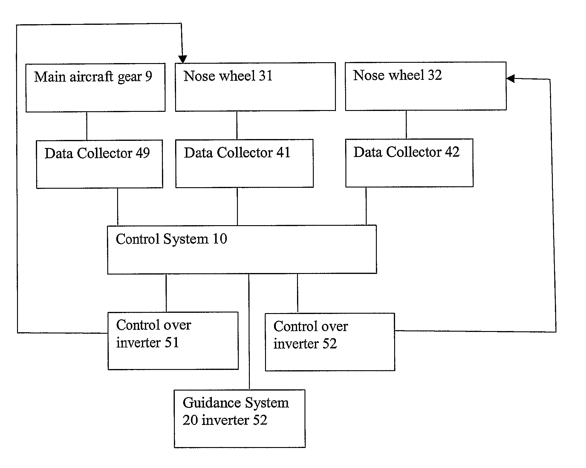
[0026] In the present invention, one or more motors power the nosegear. In a preferred embodiment each wheel of the nosegear houses an independently driven motor. The m...


PUM


Abstract

The present invention describes a drive system for an aircraft involving one or more nose wheel motors. Data regarding the nose wheel rotation is used to control the ground travel of the aircraft, to predict potential problems, to provide more precise control over the aircraft, and to improve aircraft safety.

Description

TECHNICAL FIELD [0001] The present invention relates to motors located within the nose wheel of an aircraft, and the use of motor speed sensors attached to the nose wheel motor. BACKGROUND ART [0002] The use of small compact electric motors inside, or in close proximity to, an aircraft wheel, for direct drive, presents a problem relating to the provision of the required amounts of torque. Generally, for moving an aircraft from rest, the torque required is extremely high, so that the torque versus speed characteristics of the load, and the maximum speed characteristics of the load when driven, fall well outside the ideal predicted by motor scaling laws. This means that a motor sized to produce the torque necessary for direct drive of the load will be operating at well below maximum speed, and thus well below maximum power levels. The active materials of the machine will be underutilized, the machine will be far heavier than necessary, and the machine efficiency will be poor. [0003] G...

Claims


Application Information

Patent Timeline
Patent Type & Authority Applications(United States)
IPC IPC(8): G05D1/00G06F17/00
CPCB64C25/40B64C25/34G05B1/00G05D1/02G05D1/0202G05D13/00G05D27/02
Inventor COX, ISAIAH WATASCARMAN JR., ROBERT LINCOLN
Owner BOREALIS TECH LTD
Why Eureka
Try Eureka