Supercharge Your Innovation With Domain-Expert AI Agents!

Rotary Circuit Selection Device with Crown Detent

a selection device and circuit technology, applied in the field of electromechanical switches, can solve the problems of excessive play in the switch, the cam and the cam follower being worn, and the follower being dependent on the follower, so as to reduce the play over time

Active Publication Date: 2007-12-20
ELECTRO SWITCH
View PDF8 Cites 8 Cited by
  • Summary
  • Abstract
  • Description
  • Claims
  • Application Information

AI Technical Summary

Benefits of technology

[0006] The present invention is directed toward a rotary circuit selection device having a driving cam and an opposing stationary cam. The cams each have a series of alternating peaks and valleys adapted to inhibit and reduce play over time. A biasing mechanism biases the driving cam toward the station

Problems solved by technology

A problem with this type of detent, however, is that the size of the spring biasing the cam follower is dependent upon the size of the cam follower shaft.
As with most detents, however, use of the switch causes both the cam and the cam follower to wear in a manner that causes play (i.e. movement when the cam follower is in a seated configuration) in the switch.
Excessive play in the switch is undesirable because it can cause a circuit to be inadvertently opened or closed.
Thus, there is a need for methods and devices which can use higher tension springs and which do not become less accurate due to use.

Method used


Image

  • Rotary Circuit Selection Device with Crown Detent
  • Rotary Circuit Selection Device with Crown Detent

Examples


Embodiment Construction

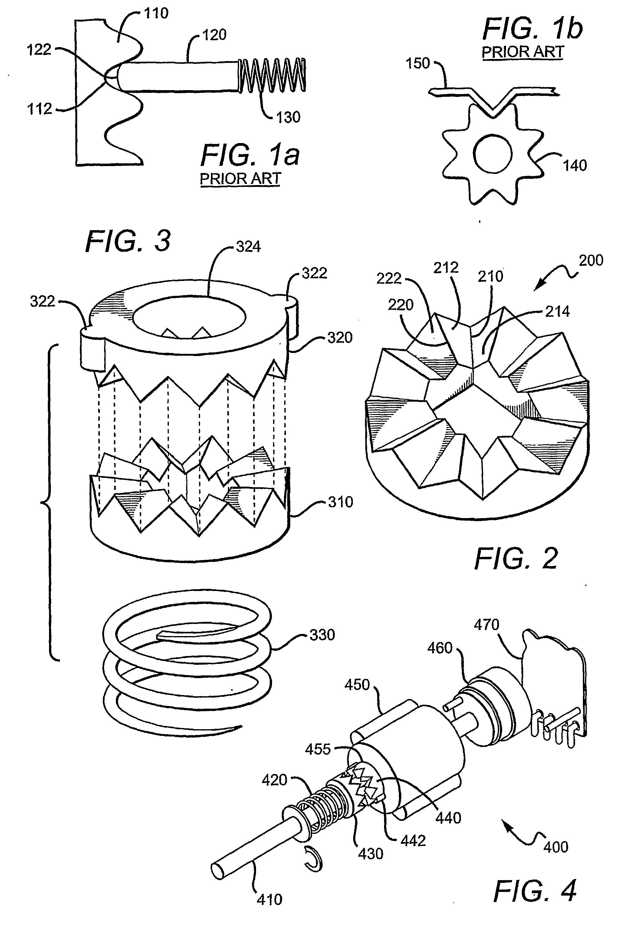
[0014]FIGS. 1a and 1b are examples prior art detent mechanisms. The detent mechanism of FIG. 1a comprises a cam 110, a cam follower 120, and a spring 130. In operation, cam follower 120 will follow the contour of cam 110 as the cam is rotated. It should be recognized that the cam follower will cause wear in the peaks and valleys of the cam as it moves over those areas. Additionally, it can be observed that the tip of the cam follower 122 will not contact the valley 112 until substantial wear has occurred. Wear causes relatively more play in a detent mechanism, however, causing it to become less accurate over time and eventually making it unsuitable for its intended purpose.

[0015]FIG. 1b is an alternative prior art detent having a cam 140 and a cam follower 150. Here, the cam follower 150 follows the outside contour of the cam 140 as the cam rotates. Again, however, wear will cause additional play in the switch rendering it less accurate over time.

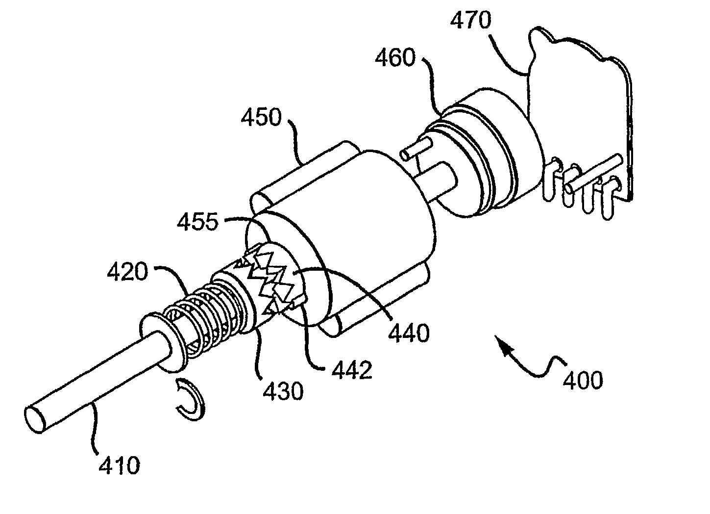
[0016]FIG. 2 is an annular cam 200...


PUM


Abstract

A rotary circuit selection device (400) having a driving cam (430) and an operating cam (440), each having a series of alternating peaks (442) and valleys (455). A biasing mechanism (420) biases the driving cam toward the stationary cam such that the peaks of one cam are received by the valleys of the other cam and vice versa. Selection of an alternative circuit includes rotating and translating the driving cam in relation to stationary cam.

Description

FIELD OF THE INVENTION [0001] The field of the invention is electromechanical switches. BACKGROUND OF THE INVENTION [0002] A rotary circuit selection device generally uses a rotating shaft connected to a terminal to make or break a connection to one or more other terminals. In performing its function, a rotary switch also uses a detent mechanism. Merriam-Webster's Online Dictionary defines a detent as “a device (as a catch, dog, or spring-operated ball) for positioning and holding one mechanical part in relation to another so that the device can be released by force applied to one of the parts”. Basically, the detent aids a user of the switch in establishing and holding a knob position that equates to a desired electrical setting. [0003] In order to set and hold a particular position, a detent often comprises a cam follower and a cam. The cam is generally an annular component with a hole in the middle. The surface of the cam that forms the hole is varied in contour. As a shaft is ro...

Claims


Application Information

Patent Timeline
IPC IPC(8): H01H19/54
CPCH01H3/40H01H19/62H01H19/11H01H19/63
Inventor HORTON, DONALD L.
Owner ELECTRO SWITCH
Features
  • R&D
  • Intellectual Property
  • Life Sciences
  • Materials
  • Tech Scout
  • Unparalleled Data Quality
  • Higher Quality Content
  • 60% Fewer Hallucinations
Learn More