
Paper feed cassette

a cassette and paper technology, applied in the field of paper feed cassettes, can solve the problems of disadvantageous likely to be curved (warped) at the center of the width direction, disadvantageous likely to be carried in a direction, etc., and achieve the effect of suppressing curvature (warpage) and inhibiting the increase of the number of components

Inactive Publication Date: 2007-12-20
FUNAI ELECTRIC CO LTD
View PDF0 Cites 8 Cited by
  • Summary
  • Abstract
  • Description
  • Claims
  • Application Information

AI Technical Summary

Benefits of technology

[0013]The present invention has been proposed in order to solve the aforementioned problems, and an object of the present invention is to provide a paper feed cassette capable of suppressing curvature (warpage) in a width direction of a paper for inhibiting the paper from being carried in an oblique direction, and inhibiting a press member pressing the paper from coming off from a paper feed cassette also in a state of a large number of the papers, while inhibiting the number of components from increase.

Problems solved by technology

In the conventional paper feed cassette proposed in the aforementioned Japanese Patent Laying-Open No. 2002-332122, however, the press member (plate spring) pressing the upper surface in the vicinity of the end in the width direction of the paper is integrally formed on the left and right inner surfaces of the paper tray, whereby the center in the width direction of the paper is not pressed, and the paper is disadvantageously likely to be curved (warped) at the center in the width direction thereof.
Thus, the paper feed cassette does not eliminate the warpage in the width direction of the paper, whereby the paper is disadvantageously likely to be carried in a direction oblique to a carrying direction due to the warpage in the width direction of the paper.
In the paper feed cassette proposed in the aforementioned Japanese Patent Laying-Open No. 2002-332122, in the case where the lid is closed in a state where a large number of papers are stored in the paper tray, loads from the papers and the above thereof is applied to the press member (plate spring) by coming into contact with the papers, and the inclined portion is further warped in a fallen direction, thereby causing deformation.
Thus, in the case where the press member presses a large number of papers, the flat portion disadvantageously peels and comes off from a lower surface of the lid as time advances.
In the conventional paper feed cassette proposed in the aforementioned Japanese Patent Laying-Open No. 2003-276863, the press member (plate spring) pressing the upper surface of the paper suppresses the excessive curl (warpage) in the width direction of the paper and does not eliminate the warpage in the width direction of the paper, whereby the paper is disadvantageously likely to be carried in the direction oblique to the carrying direction due to the warpage in the width direction of the paper.
In the conventional paper feed cassette proposed in the aforementioned Japanese Patent Laying-Open No. 2004-83175, the second press member (plate spring) pressing the upper surface in the vicinity of the end in the width direction of the paper is integrally formed on the right and left inner side surfaces of the paper tray, whereby the curvature (warpage) is disadvantageously likely to occur in the center in the width direction of the paper.
Thus, the paper is disadvantageously likely to be carried in the direction oblique to the carrying direction due to the warpage in the width direction of the paper.
In the conventional paper feed cassette proposed in the aforementioned Japanese Patent Laying-Open No. 5-229676, the spring member (coil spring) and the pushing up plate for pressing the paper stored in the paper tray against the roller mounted on the lid is required in addition to the roller, whereby the number of components is disadvantageously increased.

Method used


Image

  • Paper feed cassette
  • Paper feed cassette
  • Paper feed cassette

Examples


first embodiment

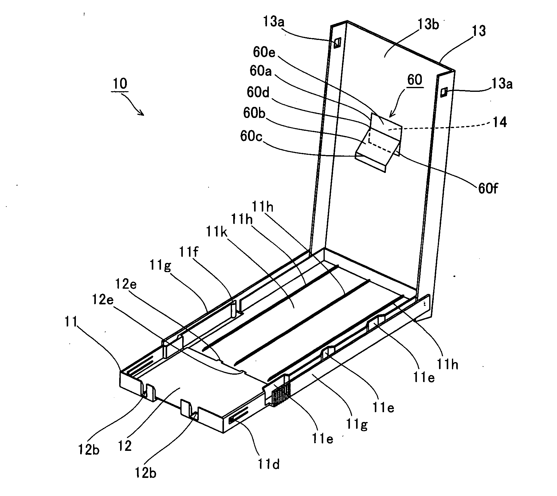
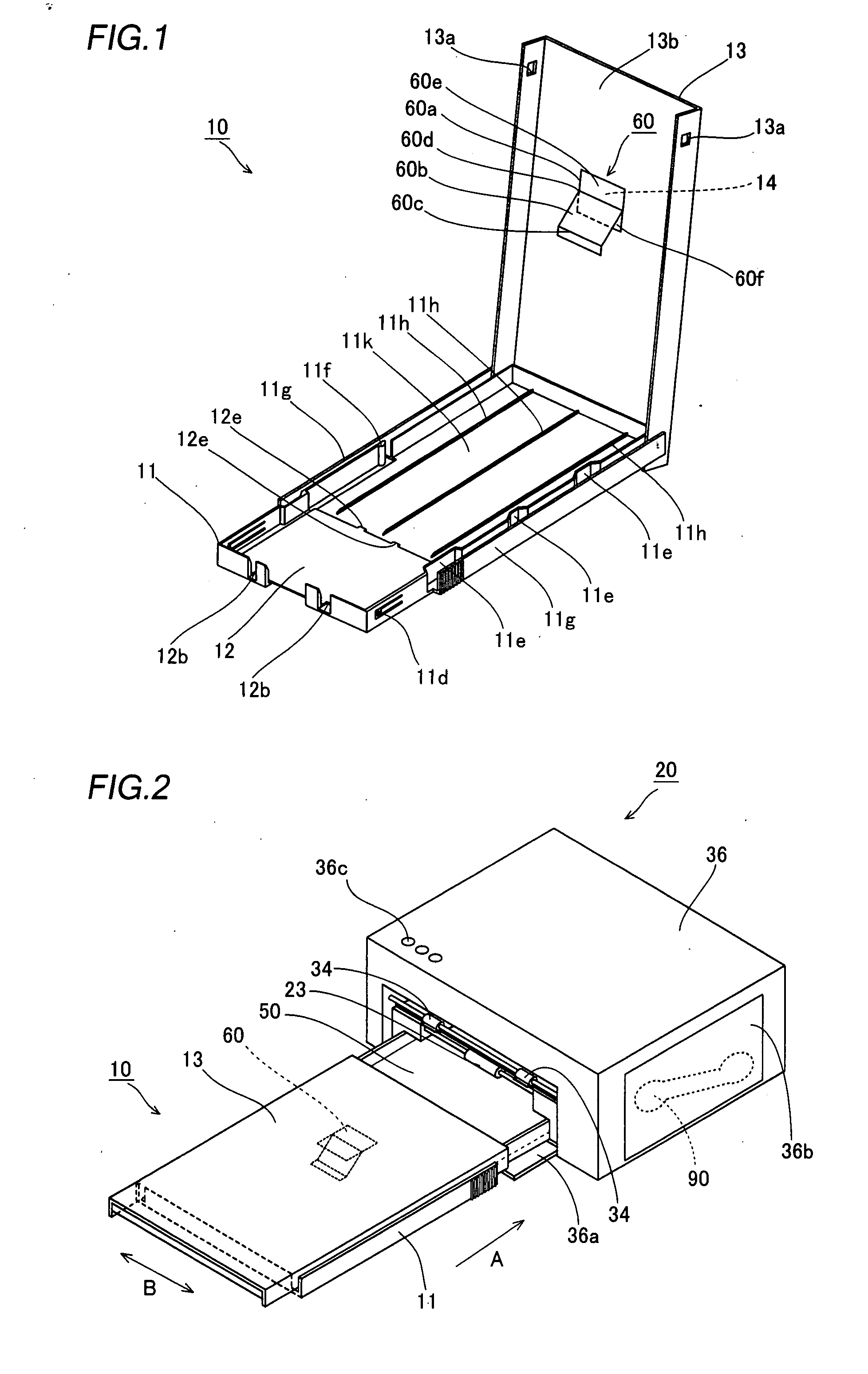
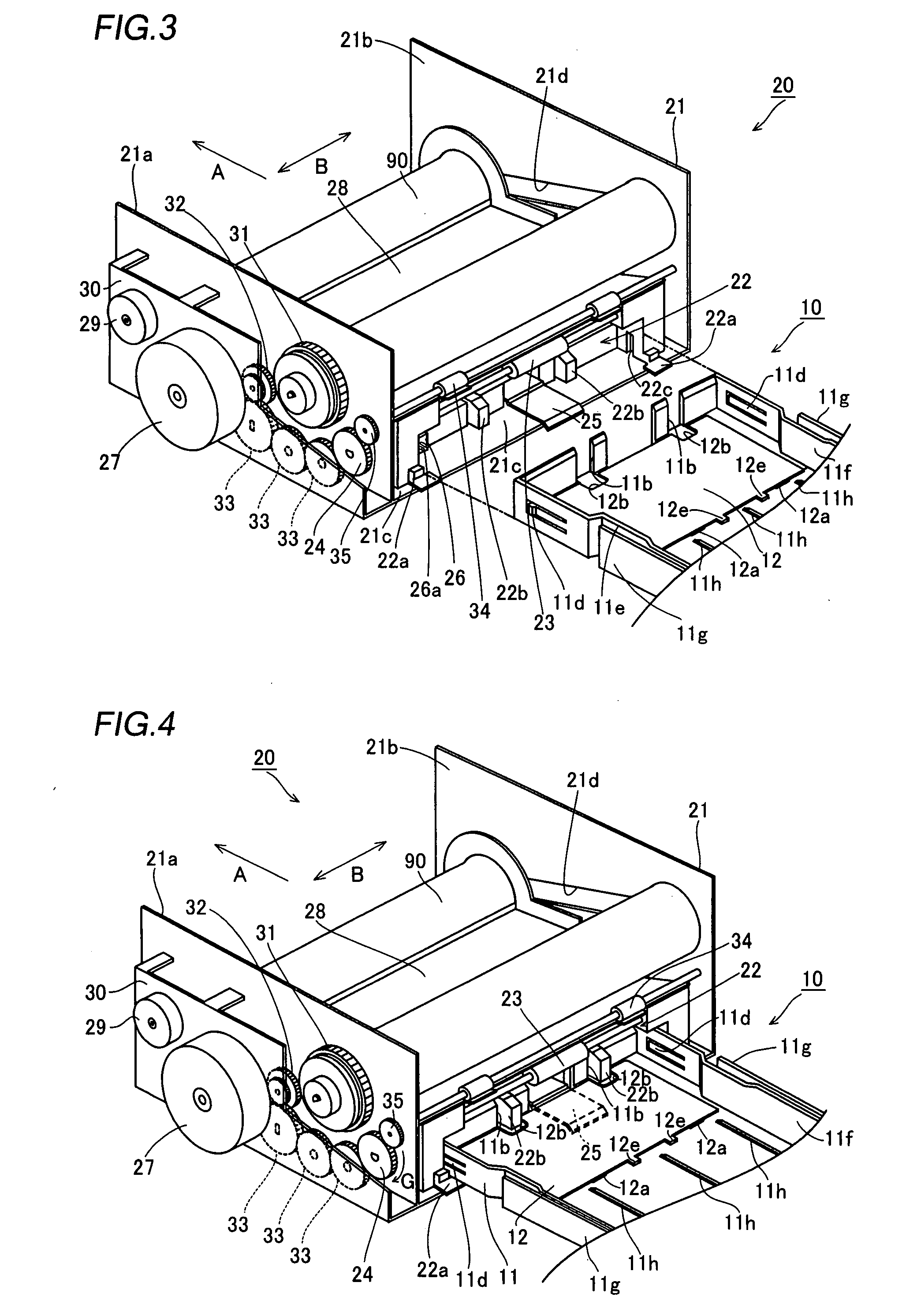
[0061]With reference to FIGS. 1 to 10, a structure of a paper feed cassette according to a first embodiment of the present invention will be now described. According to the embodiment, the present invention is applied to the paper feed cassette of a dye sublimation printer which is an exemplary image generating apparatus.

[0062]A paper feed cassette 10 according to the first embodiment of the present invention is so formed as to be detachably mounted on a dye sublimation printer 20 as shown in FIG. 2.

[0063]The paper feed cassette 10 comprises a cassette body 11 made of resin, a lift member 12 made of resin and a lid member 13 made of resin as shown in FIGS. 1 and 2. The lid member 13 made of resin is provided for inhibiting dust or the like from adhering to papers 50 and slidably mounted on the cassette body 11 as shown in FIG. 2. As shown in FIGS. 3 to 7, the cassette body 11 has a pair of engaging portions 11a (see FIG. 5) rotatably engaged with the lift member 12, a pair of notche...

second embodiment

[0098]A second press member 70 according to a second embodiment has a different structure from that of the first embodiment with reference to FIGS. 16 to 19. Structures other than the second press member 70 according to the second embodiment are similar to those according to the aforementioned first embodiment, and hence the description thereof will not be repeated.

[0099]According to the second embodiment, a second press member 70 made of resin pressing an upper surface of papers 50 is provided on a lower surface 13b of a lid member 13 independently of the lid member 13 as shown in FIG. 18. As shown in FIG. 16, a flat portion 70a of the second press member 70 includes a first flat portion 71a on the right and a second flat portion 71b on the left, between which a bonding line of the flat potion 70a and the inclined portion 70b is a boundary line. The second flat portion 71b is provided with a U-shaped cutout portion 70e in a prescribed region of a bonding portion 70d between the fir...

third embodiment

[0106]With reference to FIGS. 23 to 26, according to a third embodiment, an inclined portion 80b of the second press member 80 is supported by a support portion 80f dissimilarly to the aforementioned first and second embodiments. Structures other than the second press member 80 according to the third embodiment are similar to those according to the aforementioned first embodiment, and hence the description thereof will not be repeated.

[0107]In a paper feed cassette 10 according to the third embodiment, a second press member 80 made of resin pressing an upper surface of papers 50 is provided on a lower surface 13b of a lid member 13 independently of the lid member 13 as shown in FIG. 25. The second press member 80 includes the support portion 80f integrally bonded with a first flat portion 81a on an end on a lower surface of the first flat portion 81a, extending a direction oblique to the inclined portion 80b and bonding with the inclined portion 80b. The support portion 80f supports...


PUM


Abstract

A paper feed cassette includes a second press member for pressing the center in a width direction of an upper surface of a paper. The second press member integrally includes a flat portion mounted on the lower surface of the lid member, an inclined portion integrally bonded with the flat portion on a region other than an end in a lower surface of the flat portion, extending in an oblique direction toward an inner bottom surface of the cassette body, and having at least an elastically deformable bonding portion between the inclined portion and the flat portion and a press portion provided on a forward end of the inclined portion, and the press portion is brought into contact with the inner bottom surface of the cassette body when the lid member is arranged on the upper portion of the cassette body.

Description

BACKGROUND OF THE INVENTION[0001]1. Field of the Invention[0002]The present invention relates to a paper feed cassette, and more particularly, it relates to a paper feed cassette mounted on an image generating apparatus.[0003]2. Description of the Background Art[0004]Paper feed cassettes mounted on image generating apparatuses are known in general, as disclosed in Japanese Patent Laying-Open Nos. 2002-332122, 2003-276863, 2004-83175 and 5-229676 (1993), for example.[0005]The aforementioned Japanese Patent Laying-Open No. 2002-332122 discloses the paper feed cassette comprising a width approaching member (plate spring) pressing a side surface of a paper parallel to a paper feed direction of the paper stored in a paper tray to approach the paper to one side of the paper tray, and a rotatable lid covering an upper surface of the paper tray, in which a press member (plate spring) pressing a vicinity of both ends in a width direction of an upper surface of the paper is conceivably bonded...

Claims


Application Information

Patent Timeline
Patent Type & Authority Applications(United States)
IPC IPC(8): B65H1/04
CPCB65H1/26B65H2405/115B65H2402/5441B65H3/54B65H1/266B65H2402/54
Inventor MUSHIMOTO, ATSUSHINAITO, TAKAHIRO
Owner FUNAI ELECTRIC CO LTD
Learn More