
Scanning device

a scanning device and lens surface technology, applied in the field of scanning devices, can solve the problems of affecting the field of view, affecting the image quality of the lens, so as to achieve the effect of suppressing the field of view

Active Publication Date: 2007-10-16
ASAHI KOGAKU KOGYO KK
View PDF4 Cites 2 Cited by
  • Summary
  • Abstract
  • Description
  • Claims
  • Application Information

AI Technical Summary

Benefits of technology

"The present invention provides a scanning device that can suppress the curvature of field even if there is an error in the shape of the lens used in the image forming optical system. This is achieved by satisfying certain conditions, such as the curvature of the field being within a certain range and the collection optical system having a specific focal length. The scanning device can be used in a variety of applications, such as in a laser scanning system or a microscope."

Problems solved by technology

However, the above mentioned fθ lens formed of two plastic lenses has a drawback that if the fθ lens has a relatively wide angle of view, optical performance of the fθ lens tends to be deteriorated by a molding error because, due to the relatively wide angle of view, a first lens located on the polygonal mirror side in the fθ lens has a small radius of curvature and a relatively wide region of the fθ lens is used as an effective area.
For example, if a meniscus lens is used in the fθ lens and the meniscus lens has a molding error, the meniscus lens tends to be deformed such that the curvature of each of lens surfaces thereof becomes larger.
If the meniscus lens has such a molding error, the curvature of field also increases, and thereby the imaging quality may be deteriorated.

Method used


Image

  • Scanning device
  • Scanning device
  • Scanning device

Examples


first example

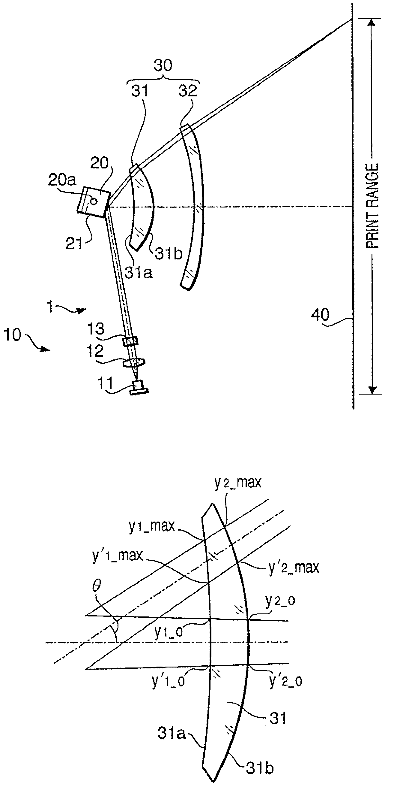
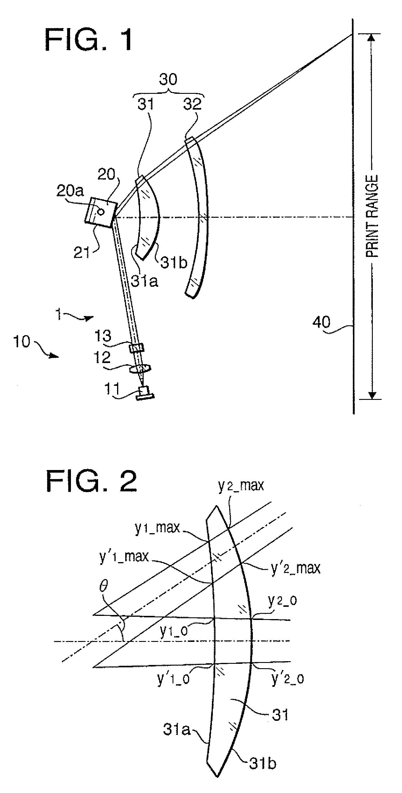
[0102]The scanning device according to a first example has the configuration shown in FIG. 1. Table 1 shows a numerical configuration of the scanning device 1 according to the first example.

[0103]

TABLE 1Radius of Circumcircle of Polygonal Mirror = 20 mmNumber of Surfaces of Polygonal Mirror = 4 surfacesAngle of Incidence = 80°, Maximum Image Height Y = 108 mmScanning Coefficient = 112.0 mm, Maximum Deflection AngleY / K = 1.04 radianSurface No.RyRzdn#1∞33.204.001.511#2∞—62.36#3∞—15.00#4−184.57—10.001.486#5−35.37—22.33#6−153.84—5.001.486#7∞−14.7982.20#8∞——

[0104]In Table 1, the character “No.” indicates surface numbers that are assigned to optical surfaces in the scanning device 1 starting from a front surface (a beam incident surface) of the anamorphic lens 13. The surface Nos. #1 and #2 denote the front surface and a rear surface (a beam emerging surface) of the anamorphic lens 13, respectively. The surfaces Nos. #3 denotes the reflective surface 21 of the polygonal mirror 20. The sur...

second example

[0115]FIG. 8 is a plan view of a scanning device 2 according to a second example. In FIG. 8, to elements which are substantially the same as those shown in FIG. 1, the same reference numbers are assigned and explanations thereof will not be repeated. Table 5 shows a numerical configuration of the scanning device 1 according to the second example. In the second example, the anamorphic lens 13 is formed to be a toric lens having a weak power in the main scanning direction.

[0116]

TABLE 5Radius of Circumcircle of Polygonal Mirror = 20 mmNumber of Surfaces of Polygonal Mirror = 4 surfacesAngle of Incidence = 80°, Maximum Image Height Y = 108 mmScanning Coefficient = 112.0 mm, Maximum Deflection AngleY / K = 1.04 radianSurface No.RyRzdn#1363.62 33.204.001.511#2∞—62.36#3∞—11.34#4−233.87—6.001.486#5−39.94—25.98#6−236.47—4.001.486#7305.53−14.7973.00#8∞——

[0117]In Table 5, the character “No.” indicates surface numbers that are assigned to optical surfaces in the scanning device 1 starting from a ...


PUM


Abstract

According to an aspect of the invention, there is provided a scanning device, which is provided with a light source unit that emits a light beam, a collection optical system that converges the light beam emitted by the light source unit principally in an auxiliary scanning direction, a deflector that deflects the light beam converged by the collection optical system, an image forming optical system that converges the light beam deflected by the deflector onto a scan target surface to form a beam spot scanning in a main scanning direction which is perpendicular to the auxiliary scanning direction. In this configuration, the scanning device satisfies a following condition: <?in-line-formulae description="In-line Formulae" end="lead"?>-1<S1-S2<1 (A)<?in-line-formulae description="In-line Formulae" end="tail"?> where S 1 = ( y 1 ⁢ _max - y 1 ⁢ _max ' ) 2 ( y 1 ⁢ _ ⁢ 0 - y 1 ⁢ _ ⁢ 0 ' ) 2 x ( 1 L 1 + 1 L ⁢ ⁢ cos ⁢ ⁢ theta ) 2 ( 1 L 1 + 1 L ) 2 , S 2 = ( y 2 ⁢ _max - y 2 ⁢ _max ' ) 2 ( y 2 ⁢ _ ⁢ 0 - y 2 ⁢ _ ⁢ 0 ' ) 2 x ( 1 L 1 + 1 L ⁢ ⁢ cos ⁢ ⁢ theta ) 2 ( 1 L 1 + 1 L ) 2 .

Description

BACKGROUND OF THE INVENTION [0001]The present invention relates to a scanning device such as an LSU (Laser Scanning Unit) mounted on a laser printer, and particularly to a scanning device capable of suppressing curvature of field caused by deformation of a lens.[0002]In general, a scanning device includes a light source, a deflecting unit such as a polygonal mirror, and an image forming optical system such as an fθ lens. In the scanning device, a laser beam emitted by the light source is reflected and deflected by the deflecting unit and is converged onto a scan target surface such as an outer circumferential surface of a photoconductive drum so that a beam spot formed by the image forming optical system scans on the scan target surface in a main scanning direction. By on / off modulating the laser beam, a latent image can be formed on the scan target surface.[0003]The scanning device to be used as an LSU is required to be low cost and compact in size. Therefore, in order to reduce co...

Claims


Application Information

Patent Timeline
Patent Type & Authority Patents(United States)
IPC IPC(8): G02B26/08
CPCG02B26/125
Inventor MATSUOKA, SHOHEI
Owner ASAHI KOGAKU KOGYO KK
Learn More