Remotely monitored security system

a remote monitoring and security system technology, applied in the field of security systems, can solve the problems of difficult to determine the cause of an event, limited information provided by conventional alarm monitoring services,

Inactive Publication Date: 2007-12-20
PHASE IV PARTNERS
View PDF2 Cites 230 Cited by
  • Summary
  • Abstract
  • Description
  • Claims
  • Application Information

AI Technical Summary

Benefits of technology

[0006]Various embodiments of a security system and methods are disclosed. In one embodiment the security system comprises one or more sensors coupled to an alarm panel, an alarm converter, a virtual monitor, and one or more subscriber devices. A first one of the one or more sensors is configured to send a first signal to the alarm panel in response to detecting an alarm event. In response to receiving the first signal, the alarm panel is configured to convey a second signal. In response to receiving the second signal from the alarm panel, the alarm converter is configured to transmit a third signal to the virtual monitor. In response to receiving the third signal, the virtual monitor is configured to retrieve additional data associated with the alarm event and forward the retrieved data to at least one of the one or more subscriber devices.

Problems solved by technology

Conventional alarm monitoring services provide a limited amount of information to the subscriber after an alarm event.
Consequently, it may be difficult to determine the cause of an event, or if an event is a false alarm.
If the subscriber is not available on the premises when an event occurs, the subscriber may have to travel to the premises to investigate the cause of the alarm, without knowing the urgency of the situation.

Method used


Image

  • Remotely monitored security system
  • Remotely monitored security system
  • Remotely monitored security system

Examples


Embodiment Construction

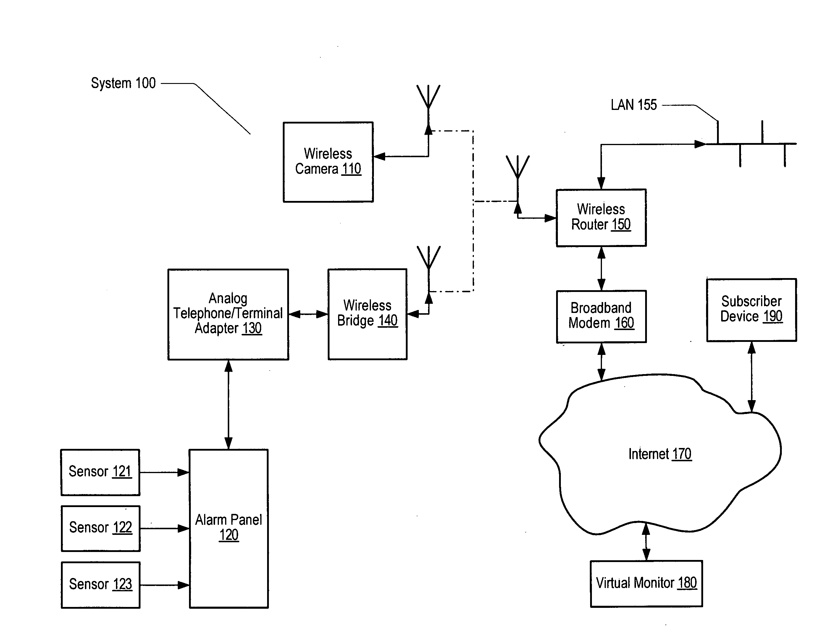
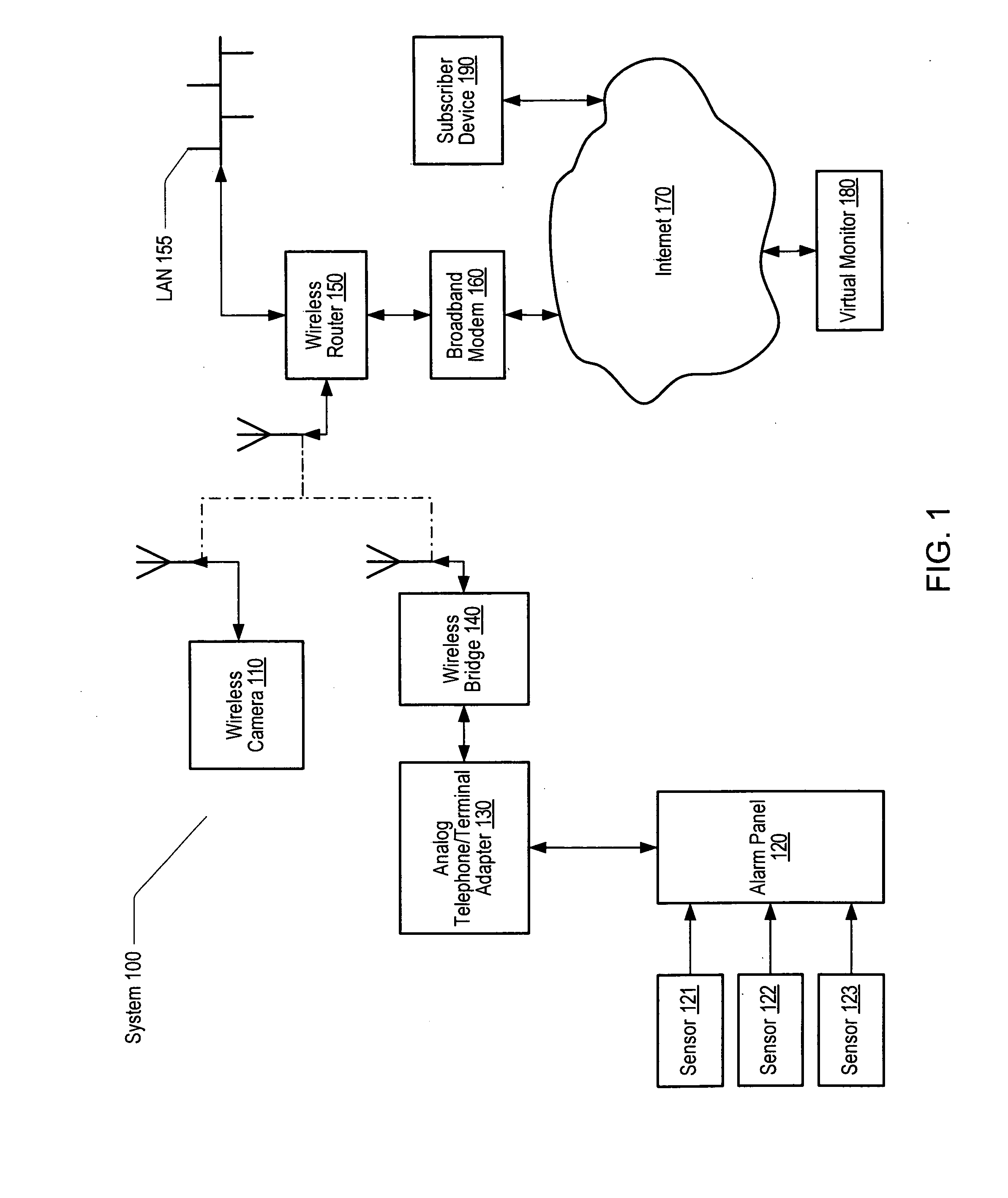
[0018]FIG. 1 is a generalized block diagram of one embodiment of a security system 100. For purposes of discussion, the systems and methods will be described within the confines of a home. However, those skilled in the art will appreciate the systems and methods may be used in association with any premises. The illustrated system includes a wireless camera 110 and an alarm panel 120. In one embodiment, sensors 121-123 may be coupled to alarm panel 120. Sensors 121-123 may be any of a variety of devices including door and window contacts, glass break detectors, motion detectors, smoke and gas detectors, “latchkey” tags, or any other suitable device. In alternative embodiments, one or more sensors may further be coupled to or incorporated into devices such as wireless camera 110. Further, one or more of the devices may have wireless, power line, or other communication mechanisms built into the device. Alarm panel 120 may be further coupled to an analog to digital conversion device, su...


PUM


Abstract

A security system and methods are disclosed. The system comprises sensors coupled to an alarm panel, an alarm converter, a virtual monitor, and one or more subscriber devices. A first sensor sends a first signal to the alarm panel in response to detecting an alarm event. In response to receiving the first signal, the alarm panel conveys a second signal. In response to receiving the second signal, the alarm converter transmits a third signal to the virtual monitor. In response to receiving the third signal, the virtual monitor retrieves additional data associated with the alarm event and forwards the retrieved data to a subscriber device. In a further embodiment, the security system comprises one or more data recording devices from which the virtual monitor retrieves the addition data. In a still further embodiment, at least one of the data recording devices is a video camera configured to store video.

Description

BACKGROUND OF THE INVENTION[0001]1. Field of the Invention[0002]This invention relates to security systems and, in particular, to systems and methods of monitoring premises via internet-connected devices.[0003]2. Description of the Related Art[0004]It has become common to use a variety of electronic devices to provide security and monitoring within and around the home, office, or other premises. In addition to conventional door and window contacts, glass break detectors, motion detectors, smoke and gas detectors, and the like, a variety of compact video cameras are also in use in home security and monitoring applications. Typically, outputs from these devices and sensors are brought together at an alarm control panel located on the premises. Often, the control panel is connected to a telephone line via which a call may be automatically placed to a monitoring service if an alarm event occurs (e.g., burglary or other intrusion). Responsive to receiving notification of an event, a moni...

Claims


Application Information

Patent Timeline
Patent Type & Authority Applications(United States)
IPC IPC(8): G08B29/00G08B1/00
CPCG08B13/1968G08B25/14G08B25/08G08B13/19695
Inventor GURLEY, SCOTT A.
Owner PHASE IV PARTNERS
Why Eureka
Try Eureka