Image display apparatus, head-mounted display, and optical axis adjustment method

a display apparatus and display head technology, applied in the field of image display apparatus, headmounted display, optical axis adjustment method, can solve the problems of deteriorating luminance degrading quality of an observed image, and difficulty of observers in observing displayed images, so as to avoid luminance deterioration and image quality degradation of an observed image

Inactive Publication Date: 2007-12-20
KONICA MINOLTA INC
View PDF3 Cites 31 Cited by
  • Summary
  • Abstract
  • Description
  • Claims
  • Application Information

AI Technical Summary

Benefits of technology

[0014]The present invention has been made to solve the problem described above, and it is an object of the invention to provide an image display apparatus capable of avoiding luminance deterioration and image quality degradation of an observed image caused by optical axis adjustment, a head-mounted display including this image display apparatus, and an optical axis adjustment method.

Problems solved by technology

In this condition, if respective positions of optical axes of right and left optical systems shift whereby an angle formed by the pair of right and left optical axes deviates from a criterion, the observer has difficulty in observing the displayed images by superimposing them on each other.
Thus, the luminance of an observed image may deteriorate, or the quality of the observed image may degrade due to occurrence of great aberration.
Moreover, the shift of the position of the optical pupil E relative to the lens 103 results in use of a portion remotely separated from a portion of the lens 103 designed so as to suppress occurrence of aberration (to transmit light), thus causing great aberration.

Method used


Image

  • Image display apparatus, head-mounted display, and optical axis adjustment method
  • Image display apparatus, head-mounted display, and optical axis adjustment method
  • Image display apparatus, head-mounted display, and optical axis adjustment method

Examples


first embodiment

[0056]One embodiment of the present invention will be described below, with reference to the accompanying drawings. First, the present embodiment will be described, mainly focusing on principles of optical axis adjustment achieved by an image display apparatus of the invention.

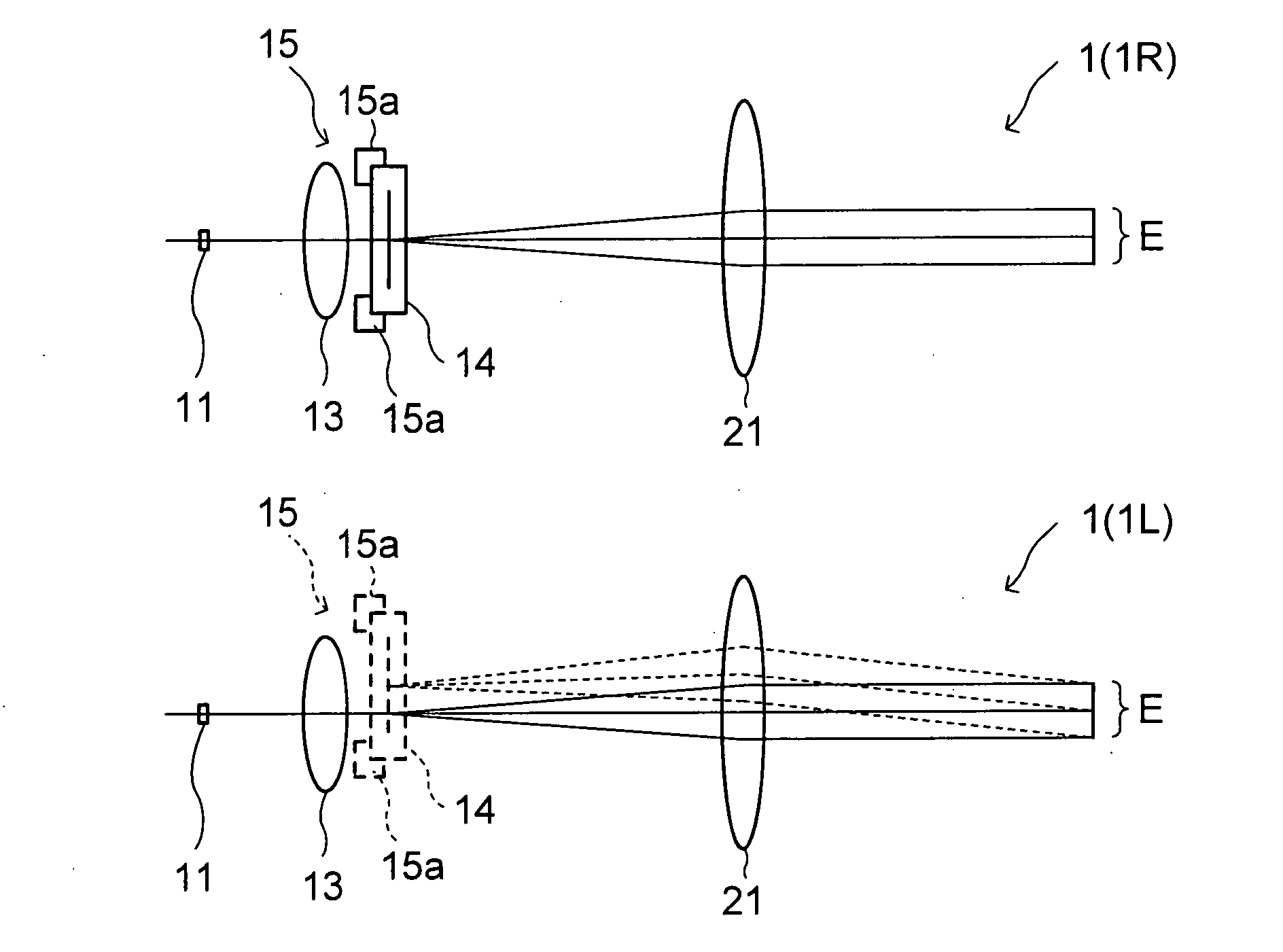
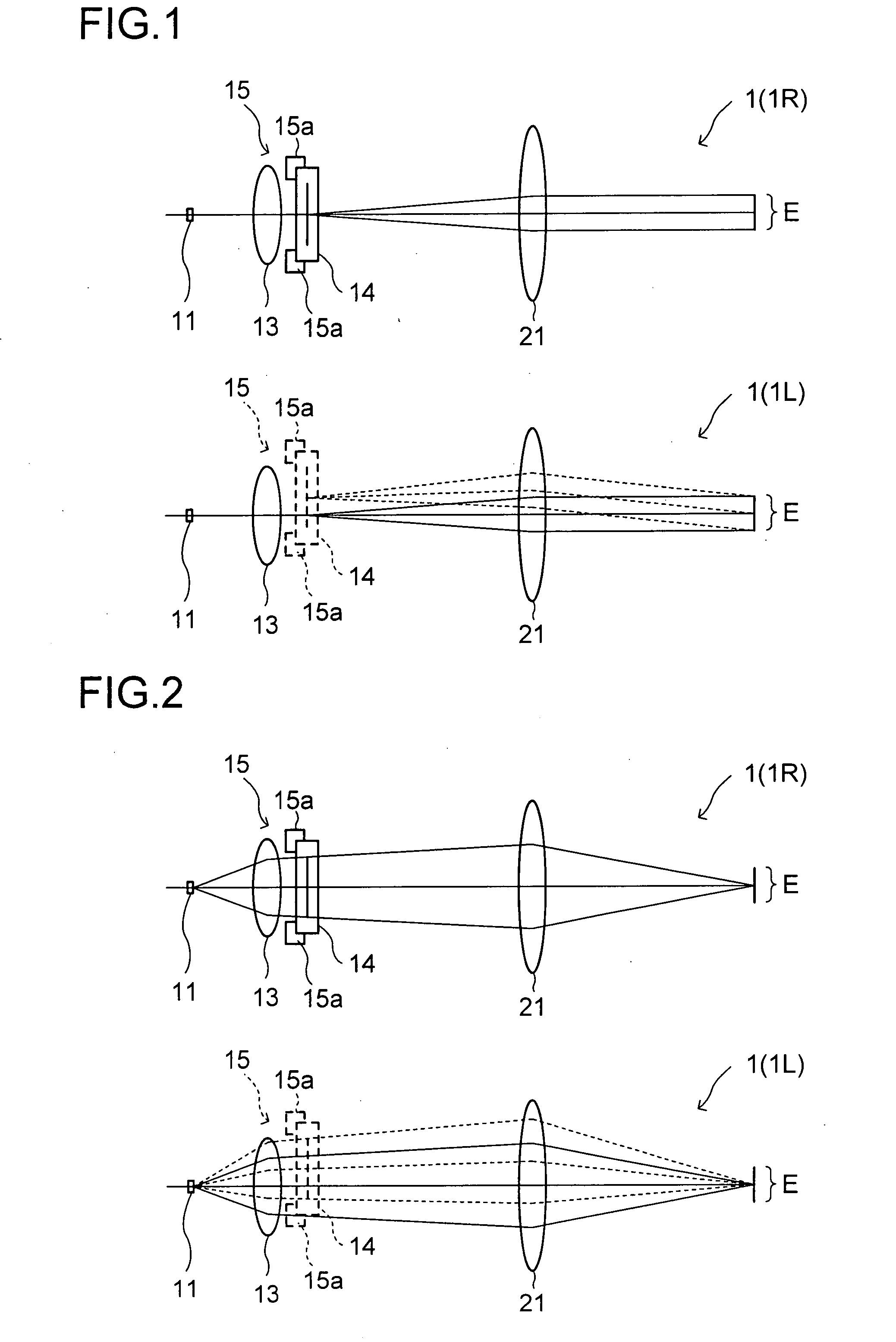
[0057]FIG. 1 is an explanatory diagram showing expanded optical paths of light exiting from the centers of display regions of display devices 14 in a right-eye image display apparatus 1R and a left-eye image display apparatus 1L of the present embodiment. FIG. 2 is an explanatory diagram showing expanded optical paths of light emitted from light sources 11 of the respective image display apparatuses 1R and 1L.

[0058]The image display apparatus 1 of the present embodiment is composed of the image display apparatuses 1R and 1L which guide light of displayed images respectively to the right and left eyes of an observer. Each of the image display apparatuses 1R and 1L has: the light source 11, a condensing lens 13,...

second embodiment

[0083]Another embodiment of the present invention will be described below, with reference to the accompanying drawings. For explanatory purposes, members with the same configuration as those in the first embodiment are provided with the same numerals. The configuration not mentioned in the first embodiment will be described as appropriate. Basic configuration of the image display apparatus 1 of the present embodiment is the same as that of the first embodiment, and is a more detailed version of the first embodiment.

(1. Configuration of the Image Display Apparatus)

[0084]FIG. 9 is a sectional view showing general configuration of the image display apparatus 1 (the image display apparatuses 1R and 1L). FIG. 10 is an explanatory diagram showing an optical path optically expanded in one direction in the image display apparatuses 1R and 1L. The image display apparatuses 1R and 1L each have a light source 11, a one direction diffuser plate 12, a condensing lens 13, a display device 14, an ...

third embodiment

[0151]Still another embodiment of the invention will be described below, with reference to the accompanying drawings. Members with the same configuration as those of the first or second embodiment are provided with the same numerals, and thus omitted from the description.

[0152]FIG. 23 is an explanatory diagram showing an optical path optically expanded in one direction in the image display apparatuse 1 (the image display apparatuses 1R and 1L) of the present embodiment. In the present embodiment, the image display apparatus 1 is configured in the same manner as that in the second embodiment except for that the light source 11 is composed of two light source groups 11P and 11Q. That is, also in the present embodiment, an optical axis adjustment mechanism 15 the same as that of the second embodiment is provided. Hereinafter, the description will be given, focusing on portions different from those in the second embodiment.

[0153]FIG. 24 shows a plan view of the light source 11 in the pr...


PUM


Abstract

At least one of right and left image display apparatuses is provided with an optical axis adjustment mechanism. The optical axis adjustment mechanism changes relative positional relationship between an image displayed on a display device and an ocular optical system in a direction intersecting an optical axis to thereby adjust an angle formed by a pair of right and left optical axes. In this condition, a light source is so arranged as to be substantially conjugate with an optical pupil. The optical axis adjustment mechanism changes the positional relationship described above without changing a position of the optical pupil relative to the ocular optical system. This permits, even when the apparatus is originally designed such that light intensity is high at a designed optical pupil position, achieving the light intensity at this optical pupil position even after optical axis adjustment. Moreover, since the position of the optical pupil relative to the ocular optical system is not changed through the optical axis adjustment, image light can be guided to the optical pupil by utilizing a portion of the ocular optically system designed so as to suppress occurrence of aberration.

Description

[0001]This application is based on Japanese Patent Application No. 2006-164690 filed on Jun. 14, 2006, the contents of which are hereby incorporated by reference.BACKGROUND OF THE INVENTION[0002]1. Field of the Invention[0003]The present invention relates to an image display apparatus which provides to an observer an image displayed on a display device as a virtual image, a head-mounted display (hereinafter also referred to as HMD) provided with this image display apparatus, and an optical axis adjustment method.[0004]2. Description of Related Arts[0005]Conventionally, an HMD has been proposed which permits an observer to observe images displayed on a pair of right and left display devices with his or her both eyes. When the observer is fitted with such a binocular HMD, he or she observes the right and left displayed images as one image by superimposing them on each other. In this condition, if respective positions of optical axes of right and left optical systems shift whereby an a...

Claims


Application Information

Patent Timeline
Patent Type & Authority Applications(United States)
IPC IPC(8): G02B27/22
CPCG02B27/0172G02B2027/011G02B2027/0112G02B2027/0178G02B2027/0123G02B2027/0174G02B2027/0118
Inventor TANIJIRI, YASUSHI
Owner KONICA MINOLTA INC
Why Eureka
Try Eureka