Display device having variable light shielding black matrix layer

a technology of black matrix layer and display device, which is applied in the direction of semiconductor devices, diodes, instruments, etc., can solve the problems of deteriorating contrast ratio, polarizing plate is an expensive member, and is not suitable for reducing thickness, so as to reduce power consumption, improve luminance, and increase life-span

Pending Publication Date: 2021-04-22
LG DISPLAY CO LTD
View PDF7 Cites 4 Cited by
  • Summary
  • Abstract
  • Description
  • Claims
  • Application Information

AI Technical Summary

Benefits of technology

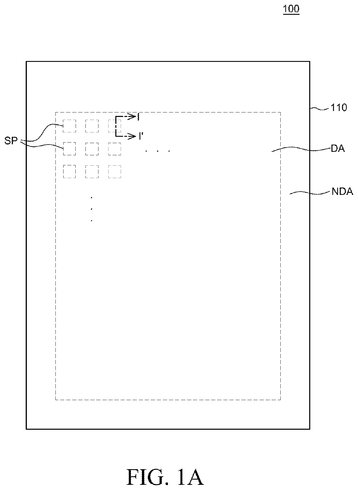
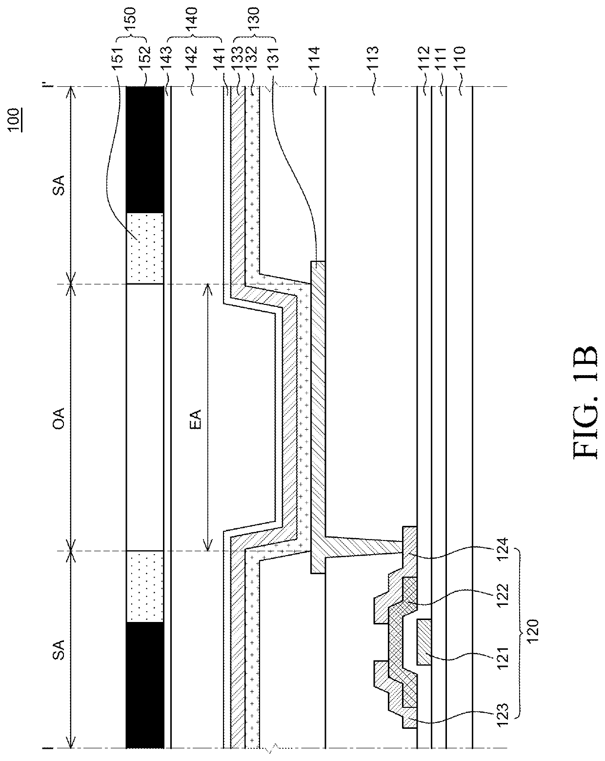
[0006]In order to supplement the problems of the polarizing plate, it has been proposed to apply a black matrix layer instead of the polarizing plate. The black matrix layer absorbs external light to have a reflectance and a reflective visibility which are equal to those of the polarizing plate, but transmits light emitted from the emission area through an opening to reduce power consumption, increase life-span, and improve luminance. When the black matrix layer is applied, as a width of the opening is smaller, a reflection area is also reduced so that a reflective visibility may be further improved. However, a part of the emission area is shielded in accordance with a viewing angle so that luminance deterioration and color distortion may be caused in accordance with a viewing angle.

Problems solved by technology

However, the cathode is formed using a metal material having a high reflectance so that the external light is reflected by the metal material to deteriorate a contrast ratio.
However, the polarizing plate is an expensive member and has a relatively large thickness so that it is not appropriate for reduction of the thickness.
Further, the polarizing plate also partially absorbs light emitted from the organic light emitting layer so that there is a limitation in lowering a driving voltage.
However, a part of the emission area is shielded in accordance with a viewing angle so that luminance deterioration and color distortion may be caused in accordance with a viewing angle.

Method used


Image

  • Display device having variable light shielding black matrix layer
  • Display device having variable light shielding black matrix layer
  • Display device having variable light shielding black matrix layer

Examples


Embodiment Construction

[0034]Advantages and characteristics of the present disclosure and a method of achieving the advantages and characteristics will be clear by referring to exemplary aspects described below in detail together with the accompanying drawings. However, the present disclosure is not limited to the exemplary aspects disclosed herein but will be implemented in various forms. The exemplary aspects are provided by way of example only so that those skilled in the art can fully understand the disclosures of the present disclosure and the scope of the present disclosure. Therefore, the present disclosure will be defined only by the scope of the appended claims.

[0035]The shapes, sizes, ratios, angles, numbers, and the like illustrated in the accompanying drawings for describing the exemplary aspects of the present disclosure are merely examples, and the present disclosure is not limited thereto. Like reference numerals generally denote like elements throughout the specification. Further, in the f...


PUM

PropertyMeasurementUnit
surface roughnessaaaaaaaaaa

Abstract

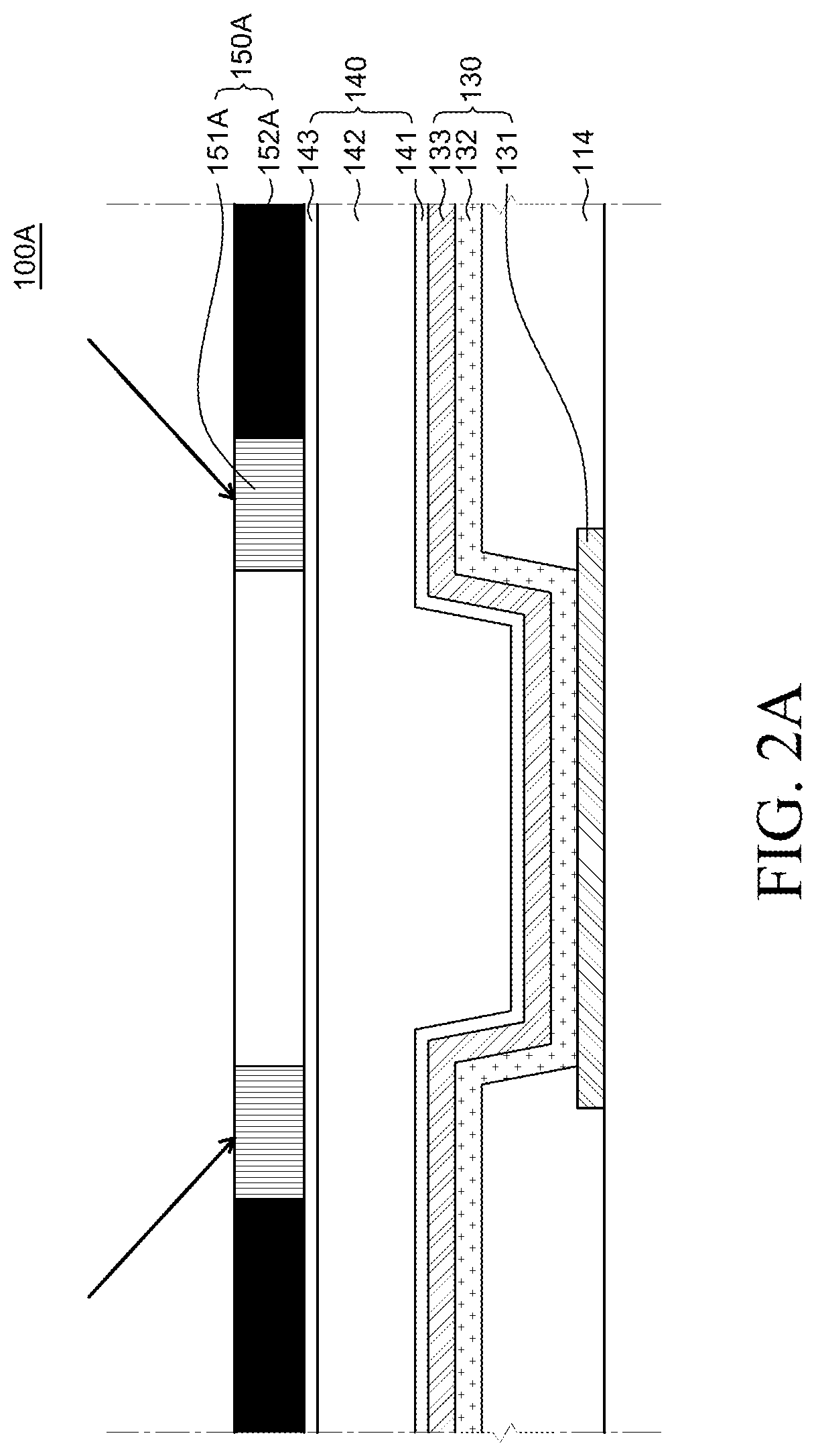
A display device includes a substrate, a thin film transistor, a first electrode, an organic light emitting layer, a second electrode and a black matrix layer which is includes a shielding area and an opening area. The opening area is formed in a position corresponding to an emission area where light is emitted from the organic light emitting layer and the shielding area includes a variable light shielding unit which is adjacent to the opening area and has a light transmittance varying in accordance with a wavelength of incident light and a light shielding unit with a constant light transmittance.

Description

CROSS-REFERENCE TO RELATED APPLICATION[0001]This application claims the priority of Korean Patent Application No. 10-2019-0131171 filed on Oct. 22, 2019, which is hereby incorporated by reference in its entirety.BACKGROUNDField of the Disclosure[0002]The present disclosure relates to a display device including a variable light shielding black matrix layer, and more particularly, to a display device including a variable light shielding black matrix layer in which a light transmittance varies depending on a wavelength of incident light to be change to a transmission mode and a shielding mode.Description of the Background[0003]Unlike a liquid crystal display device (LCD) which includes a backlight, an organic light emitting display device (OLED) does not require a separate light source. Therefore, the organic light emitting display device can be manufactured to be light and thin and has process advantages and has advantages in terms of power consumption due to the low voltage driving. ...

Claims


Application Information

Patent Timeline
Patent Type & Authority Applications(United States)
IPC IPC(8): H01L27/32G02F1/01
CPCH01L27/3232G02F1/0126H01L27/3272H10K59/12H10K50/865H10K50/86H10K2102/00H10K59/50H10K59/126
Inventor SHIN, YOUNGSUBKIM, KEUNYOUNG
Owner LG DISPLAY CO LTD
Why Eureka
Try Eureka