

Illumination device and method of making the device
a technology of led-based illumination and a mounting device, which is applied in the direction of coupling device connection, lighting and heating apparatus, lighting heating/cooling arrangements, etc., can solve the problem of non-uniform intensity of light from such an led-based illumination devi
- Summary
- Abstract
- Description
- Claims
- Application Information
AI Technical Summary
Problems solved by technology
Method used
Image

Examples
Embodiment Construction
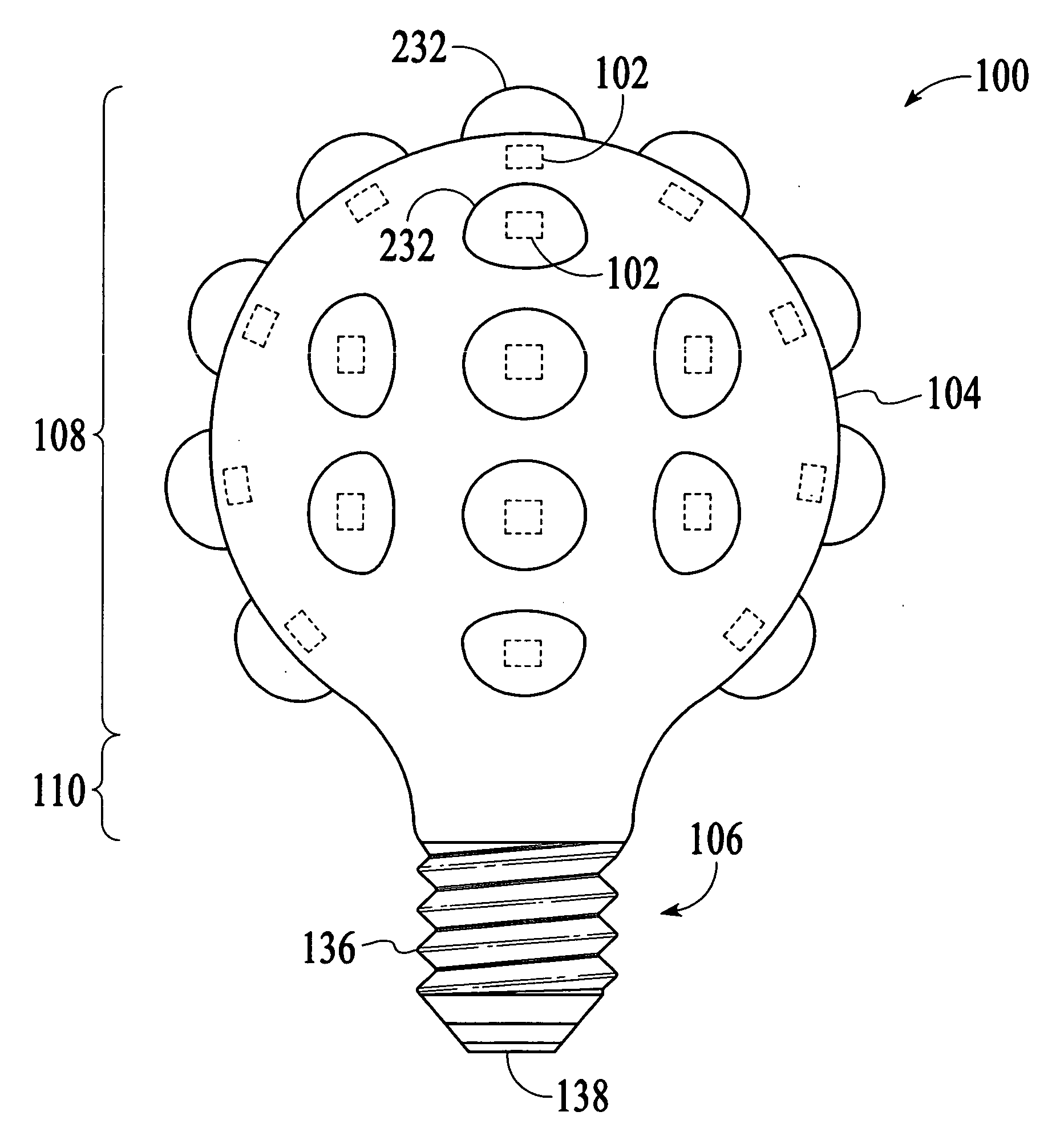
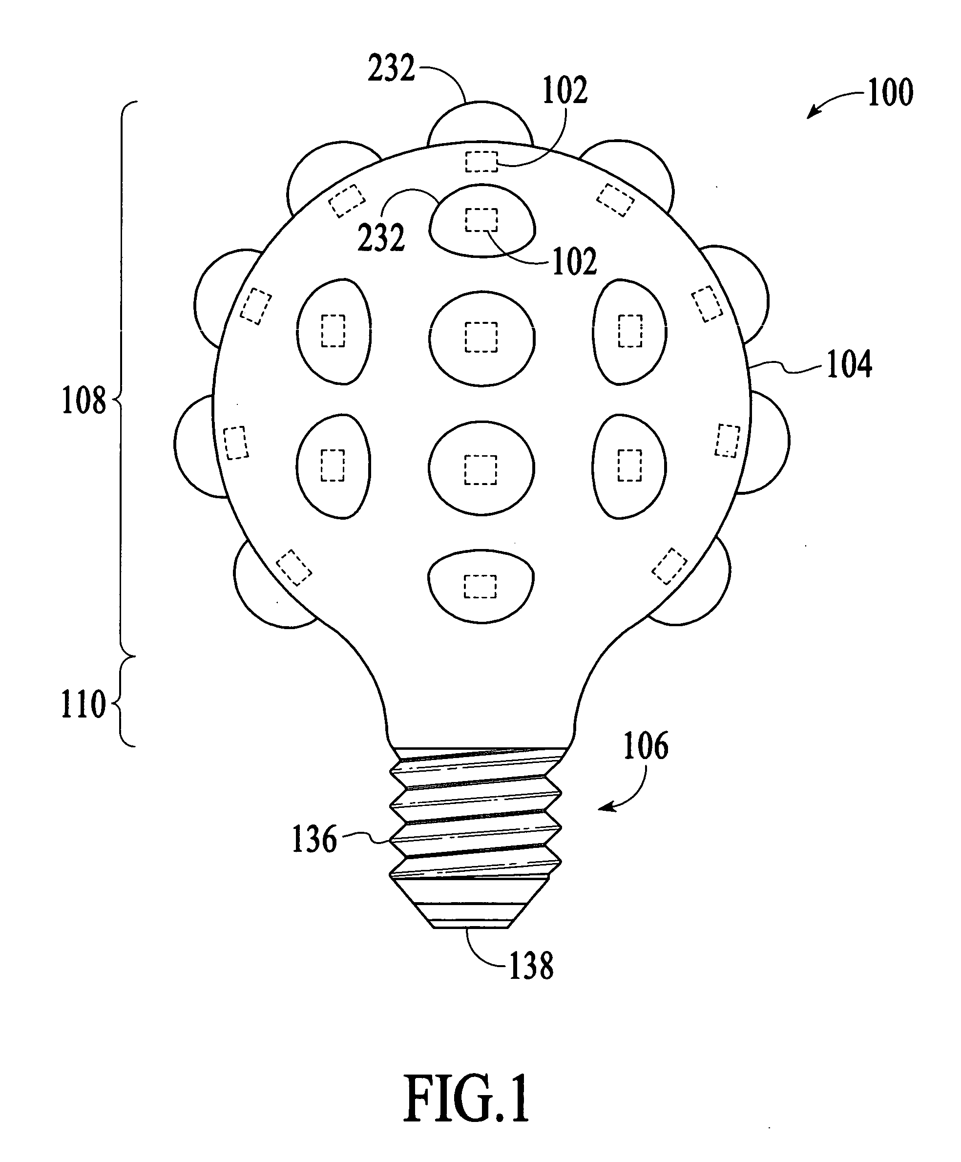
[0015]With reference to FIG. 1, an illumination device100 in accordance with an embodiment of the invention is described. The illumination device 100 includes a number of light-emitting dies 102, which may be light-emitting diode (LED) dies or laser diodes, to emit light in multiple directions to produce a multi-directional illumination similar to that of conventional incandescent light bulbs. In the embodiment illustrated in FIG. 1, the illumination device 100 is configured to produce a substantially spherical illumination, which provides light in virtually all directions from the illumination device.
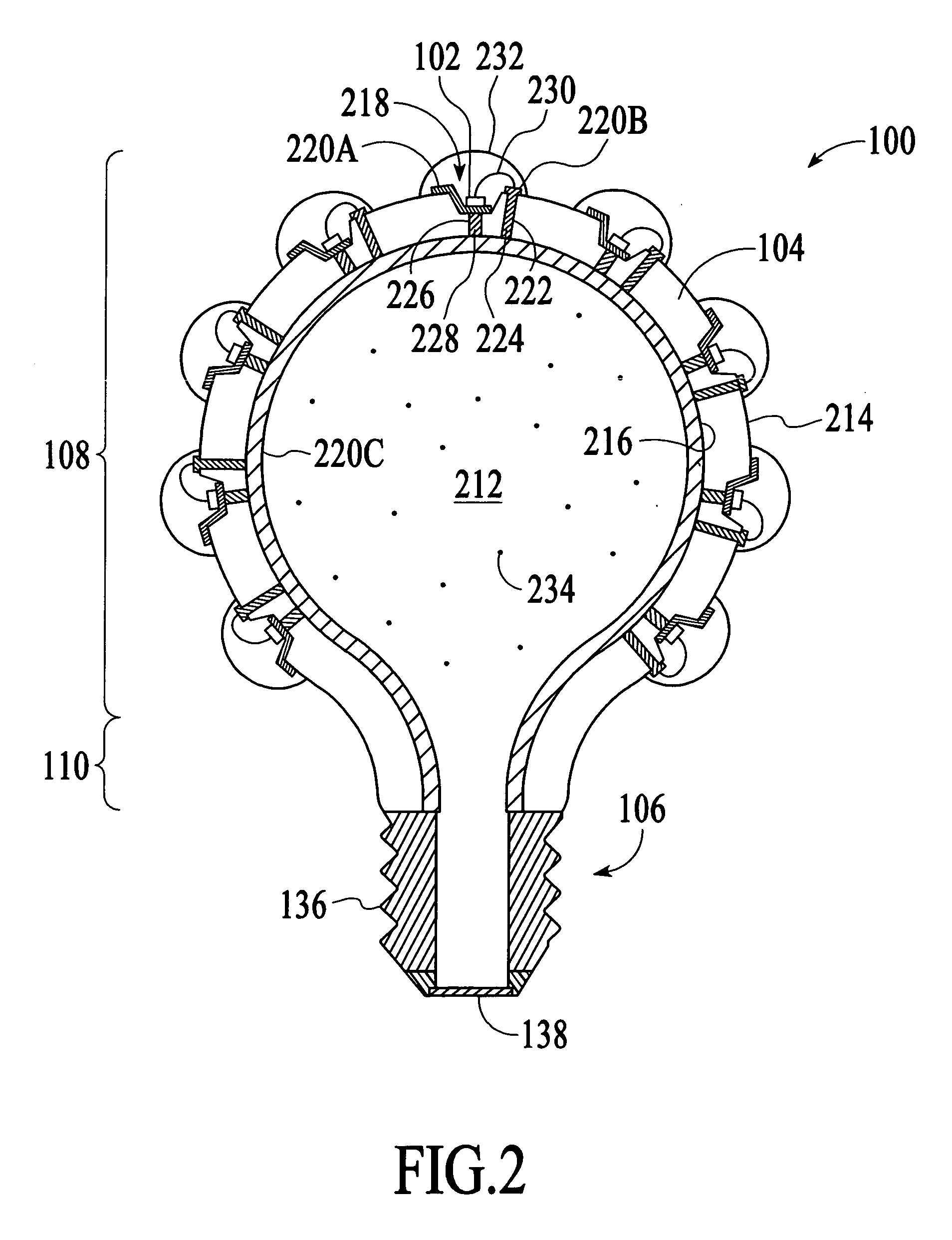
[0016]As shown in FIG. 1, the illumination device 100 includes a three-dimensional (3D) substrate 104, the light-emitting dies 102 and a screw cap 106. The 3D substrate 104 is the main structure of the illumination device 100. The 3D substrate 104 is a bulb-shaped structure. In the embodiment illustrated in FIG. 1, the 3D substrate 104 has a shape similar to the glass envelope of a typ...
PUM
 Abstract
Description
Claims
Application Information