Tire pressure monitoring apparatus

a technology of tire pressure monitoring and monitoring apparatus, which is applied in the direction of tire measurement, vehicle components, transportation and packaging, etc., to achieve the effect of facilitating pivotal movemen

Inactive Publication Date: 2007-12-27
TRW AUTOMOTIVE US LLC +1
View PDF21 Cites 63 Cited by
  • Summary
  • Abstract
  • Description
  • Claims
  • Application Information

AI Technical Summary

Benefits of technology

[0005] The present invention relates to a tire pressure monitoring apparatus. The tire pressure monitoring apparatus includes a pressure transducer and a valve stem. A support bracket connects the valve stem to the pressure transducer and facilitates pivota...

Problems solved by technology

The challenge for the TPM sensor is providing a single TPM sensor configuration that is capable of being mounted rigidly to a wide rang...

Method used


Image

  • Tire pressure monitoring apparatus
  • Tire pressure monitoring apparatus
  • Tire pressure monitoring apparatus

Examples


Embodiment Construction

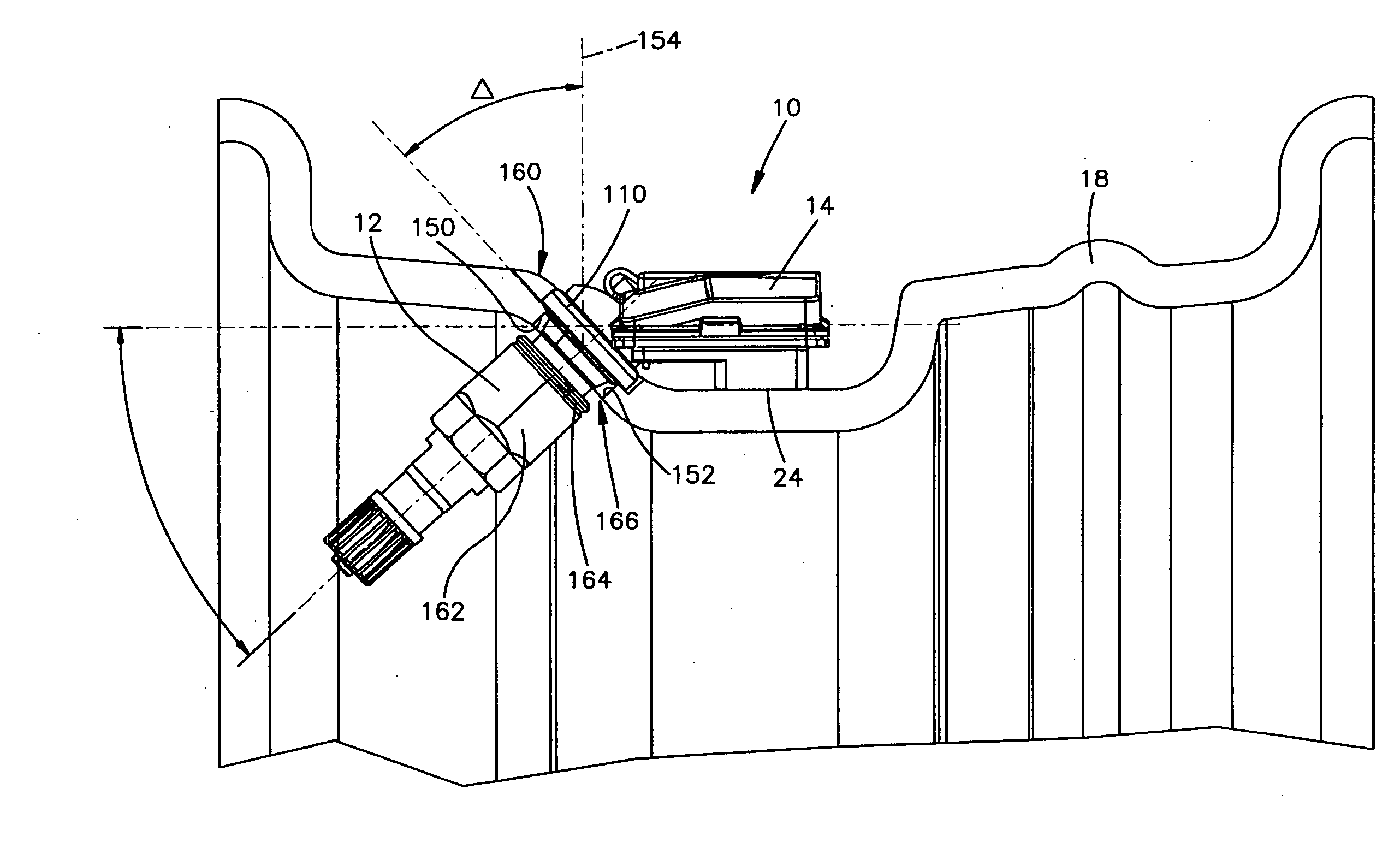
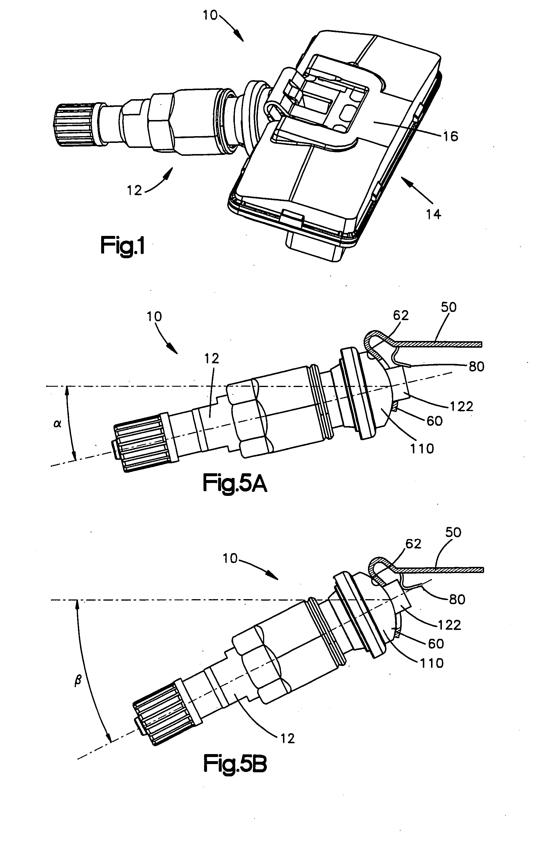
[0014] Referring to FIGS. 1 and 2, according to a first embodiment of the present invention, a tire pressure monitoring (“TPM”) apparatus or sensor 10 includes a valve stem 12 and a pressure transducer 14 with a housing 16. The TPM sensor 10 is configured to be mounted on a vehicle wheel 18 (FIGS. 6A and 6B) in a manner described in further detail below. The valve stem 12 includes a valve mechanism (not shown) that allows for selectively inflating or deflating a tire (not shown) mounted on the wheel 18, as known in the art. The pressure transducer 14 is operative to sense the inflation pressure of the tire and provide a signal, indicative of the sensed pressure, to a vehicle mounted apparatus (not shown), such as a controller.

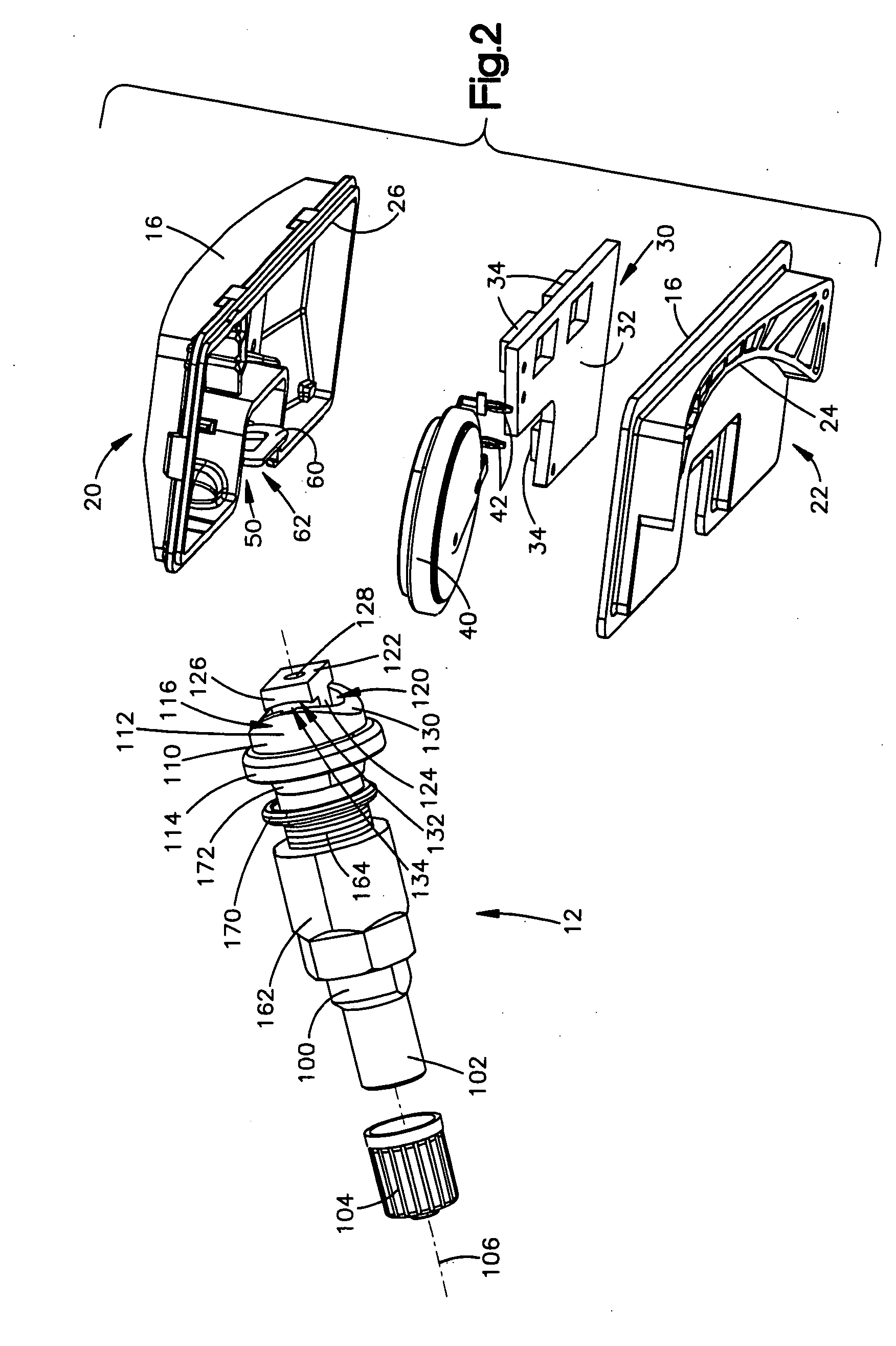
[0015] Referring to FIG. 2, the housing 16 of the pressure transducer 14 includes an upper housing part 20 and a lower housing part 22. The apparatus 10 is shown inverted in FIG. 2 so as to illustrate a lower wheel engaging surface 24 of the lower housing part...


PUM


Abstract

A tire pressure monitoring apparatus (10) includes a pressure transducer (14) and a valve stem (12). A support bracket (50) connects the valve stem (12) to the pressure transducer (14) and facilitates pivotal movement between the valve stem and the pressure transducer. The support bracket (50) includes a valve stem biasing member (80) that exerts a spring bias on the valve stem (12) to help maintain a selected angular position of the valve stem relative to the pressure transducer (14).

Description

RELATED APPLICATION [0001] This application claims the benefit of U.S. Provisional Application Ser. No. 60 / 815,357, filed Jun. 21, 2006.TECHNICAL FIELD [0002] The present invention relates to a tire pressure monitoring apparatus and, in particular, relates to a unitized tire pressure monitoring apparatus with features that facilitate installation on various vehicle wheel configurations. BACKGROUND OF THE INVENTION [0003] Tire pressure monitoring (“TPM”) systems are known in the art. There have been several mounting arrangements proposed for these TPM systems and apparatuses. Some of the proposed mounting arrangements are shown in U.S. Pat. No. 6,163,255, No. 6,722,409, No. 6,568,259, and No. 6,799,455. [0004] The automotive industry is driving to reduce the number of part numbers used for vehicle assembly. The industry is also attempting to reduce labor in plants and cost from suppliers for purchased assemblies. TPM sensors are rapidly becoming a commodity, and OEMs are attempting t...

Claims


Application Information

Patent Timeline
IPC IPC(8): B60C23/02B60C19/08
CPCB60C23/0494B60C23/0408
Inventor BLOSSFELD, MIKESCALES, JOHN
Owner TRW AUTOMOTIVE US LLC
Why Eureka
Try Eureka