Tool for coating internal surfaces of pipes

a technology for internal surfaces and pipes, applied in the field of internal coating of pipes and tubes, can solve the problems of premature corrosion of the internal surface of the pipes, premature corrosion of the finished coating, and flaws in the finished coating, and achieve the effect of facilitating pivotal movement and handling high pressur

Active Publication Date: 2020-04-09
HERNANDEZ TIBERIO
View PDF0 Cites 3 Cited by
  • Summary
  • Abstract
  • Description
  • Claims
  • Application Information

AI Technical Summary

Benefits of technology

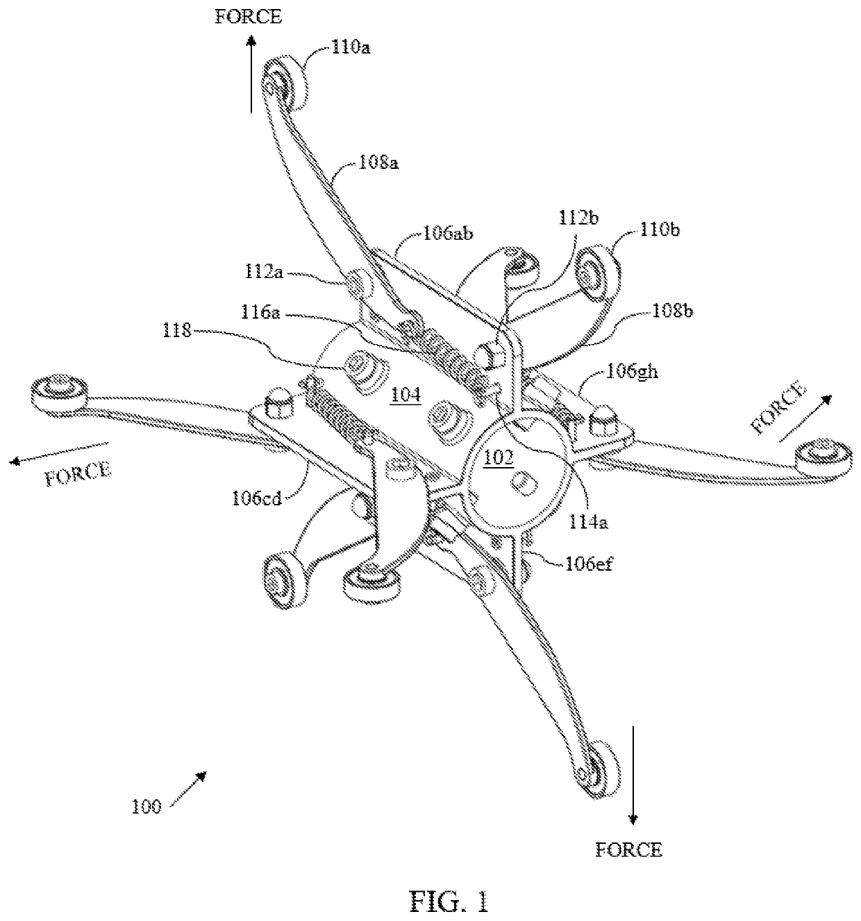
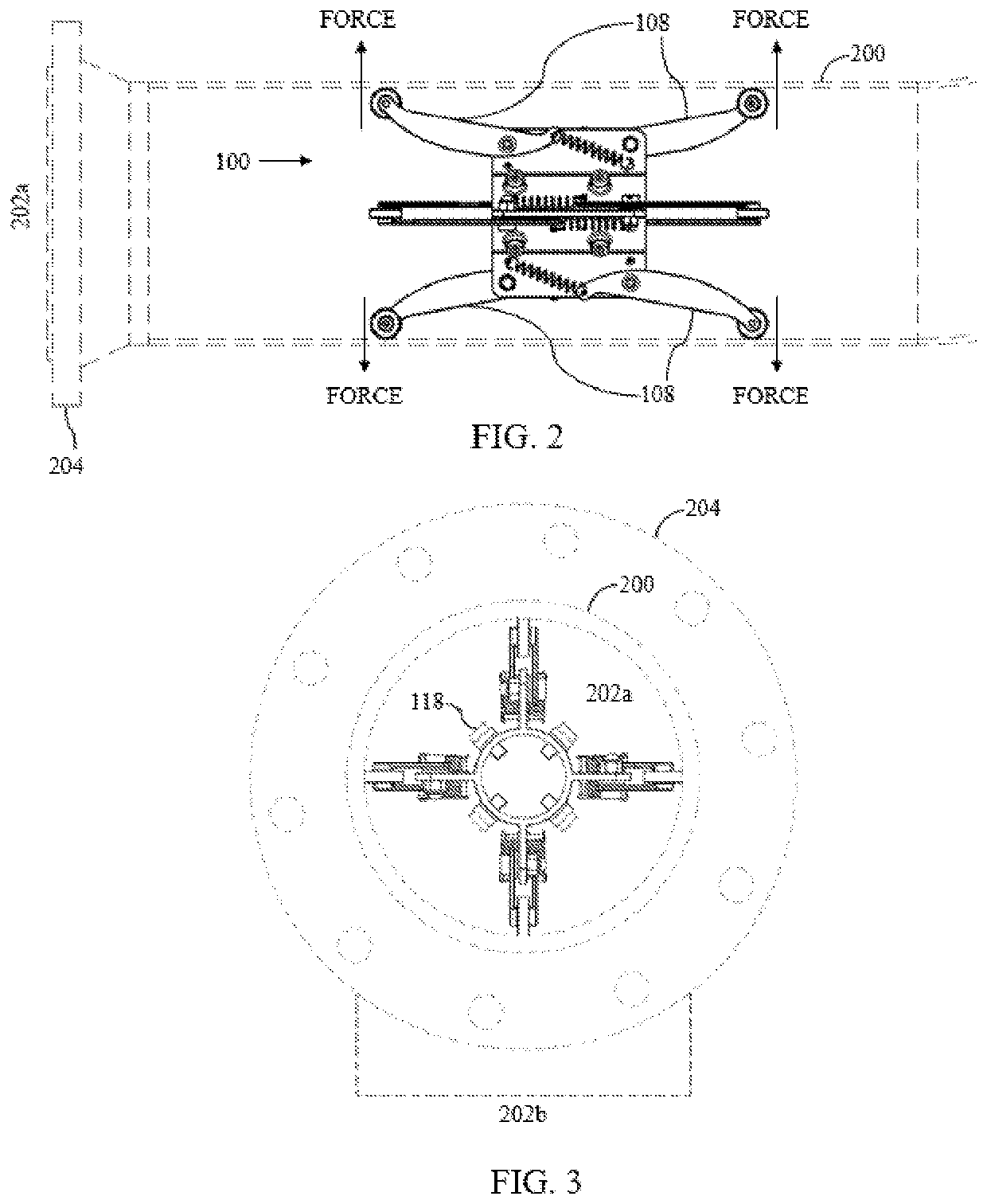
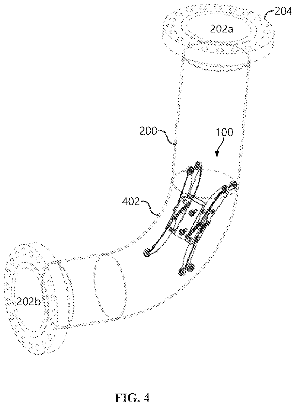
[0011]Disclosed herein is a simple tool to hold a paint spray gun, capable of handling high pressure while in operation. The tool has retracting arms which roll within the confines of the (interior of the) pipe and can maneuver within curves and angles up to 90°. Embodiments of the invention provide a tool for holding a spray painting gun for coating an internal surface of a pipe and in particular, coating the interior of curves and 90° angles of pipes. A central hub includes a hollow tube for carrying the spray painting gun. At least two projections extend outwardly from an outer surface of the hollow tube. First and second retracting arms are provided for each projection. Each retracting arm includes a roller attached a first end thereof. Further, first and second pivot pins pivotably attach the first and second retracting arms, respectively, to each projection. A retraction mechanism is provided for each retracting arm and includes first and second fixed pins provided on each projection and first and second springs that connect second ends of the first and second retracting arms to the first and second fixed pins, respectively. The retraction mechanisms facilitate a pivotal movement of the first and second retracting arms about the first and second pivot pins, respectively. In operation, the tool is inserted inside the pipe such that each roller touches the internal surface of the pipe due to an outward force exerted by each retracting arm. The tool is movable inside the pipe and carries the spray painting gun inside the pipe for facilitating coating of the internal surface thereof. Moreover, the tool adjusts automatically to different pipe diameters due to its retracting arms.

Problems solved by technology

The internal surface of the pipes may suffer premature corrosion due to coating failures.
A major cause of premature corrosion is the flaws in the finished coating, often referred to as porosity of the coating.
Manual maneuvering of the rotary paint spray guns is cumbersome, especially in cases when the pipes have long lengths.
In addition, the quality of coatings thus applied suffers due to uneven and intermittent spraying of the coating material.
While the tool can be used for painting the interior of pipes having small diameters, it suffers from certain drawbacks as discussed below.
One of the major drawbacks associated with the tools descried herein is the need to adjust the distance between arms according to varying diameters of pipes.
This adjustment requires manual efforts and undue experimentation by the technician operating the tools.
Presently, the commercially available tools do not offer a suitable solution to overcome this drawback.
In addition, since the distance between the arms (i.e., the height of the tool) is not automatically adjustable, it is difficult for the tool to maneuver around bends or angular parts of the pipes.
For example, it becomes difficult for such tools to turn around an obtuse angle of a pipe.
It becomes more difficult in cases of right angled bends in pipes.
Moreover, the typical spray painting applications entail high operating pressures and the current tools fail in withstanding such high pressures without significant mechanical robustness, thereby increasing their costs of manufacturing.
Finally, the bulky construction of the tools pose challenges when such tools are used in applications involving pipes of small diameters, for example, diameters less than about four (4″) inches or six inches (6″).
However, it should be noted that difficulties exist with current tools used to coat pipe interiors less than about ten inches (10″).

Method used


Image

  • Tool for coating internal surfaces of pipes
  • Tool for coating internal surfaces of pipes
  • Tool for coating internal surfaces of pipes

Examples


Embodiment Construction

[0020]As used in the specification and claims, the singular forms “a”, “an” and “the” include plural references unless the context clearly dictates otherwise. For example, the term “an article” may include a plurality of articles unless the context clearly dictates otherwise.

[0021]Those with ordinary skill in the art will appreciate that the elements in the Figures are illustrated for simplicity and clarity and are not necessarily drawn to scale. For example, the dimensions of some of the elements in the Figures may be exaggerated, relative to other elements, in order to improve the understanding of the present invention.

[0022]There may be additional components described in the foregoing application that are not depicted on one of the described drawings. In the event, such a component is described, but not depicted in a drawing, the absence of such a drawing should not be considered as an omission of such design from the specification.

[0023]Before describing the present invention in...


PUM

PropertyMeasurementUnit
diametersaaaaaaaaaa
anglesaaaaaaaaaa
diametersaaaaaaaaaa

Abstract

Disclosed herein is a tool for holding a spray painting instrument, such as a painting gun for painting an internal surface of a pipe. In particular, the inventive tool is ideal for painting the interior of curves and angles in a pipe and is capable of moving through and uniformly painting up to 90 degree angles of pipes or hollow tubes. The tool has a hollow central tube for carrying a spray-painting gun and at least two projections extending outwardly from an outer surface of the hollow tube. A retracting arm assembly is provided on each projection. Each retracting arm assembly includes first and second retracting arms and a corresponding force exertion mechanism. In operation, when the tool is inserted inside the pipe, each retracting arm touches the internal surface of the pipe due to an outward force exerted thereon. The tool is movable inside the pipe and adjusts automatically to different pipe diameters. The tool can be used manually or in an automated fashion to push and pull the paint gun and paint the interior of a pipe.

Description

CLAIM FOR PRIORITY[0001]This Non-provisional patent application is based on U.S. Provisional Patent Application Ser. No. 62 / 743,192, filed on Oct. 9, 2018, the priority of which is claimed, and the disclosure of which is incorporated by reference.FIELD OF THE INVENTION[0002]The present invention relates generally to internal coating of pipes and tubes, and more particularly, to a tool used for holding a spray gun for coating internal surfaces of pipes and tubes.BACKGROUND OF THE INVENTION[0003]Internal coating or painting of pipes and tubes is essential in many industries, including oil & gas and marine industries. Various pipes are applied with internal coatings to protect them from the effects of corrosion and erosion caused by the fluids carried by the pipes. The internal coatings also reduce friction and turbulence between an internal surface of the pipe and the fluid flowing therein. This in turn increases the flow efficiency of the fluid. The coatings can be of epoxy, such as ...

Claims


Application Information

Patent Timeline
Patent Type & Authority Applications(United States)
IPC IPC(8): F16L55/44B05B9/00B05B13/06
CPCB05B13/0627B05B9/007F16L2101/16F16L55/44F16L58/1027B05B13/0636B25J11/0075B05C7/08B05D7/225Y10S118/10B05B7/0093B25J5/007B05B13/06
Inventor HERNANDEZ, TIBERIO
Owner HERNANDEZ TIBERIO
Why Eureka
Try Eureka