One motor latch assembly with power cinch and power release having soft opening function

a technology of latching mechanism and motor, which is applied in the direction of electrical locking actuator, power transmission/actuation feature, incident situation lock, etc., can solve the problems of increasing the force required to release the latching mechanism, affecting the size and power requirements of the electric actuator,

Active Publication Date: 2017-03-30
MAGNA CLOSURES SPA
View PDF36 Cites 17 Cited by
  • Summary
  • Abstract
  • Description
  • Claims
  • Application Information

AI Technical Summary

Benefits of technology

[0056]Referring now primarily to FIGS. 6A and 6B, a pawl lever 566 and a closing spring 568 are shown in association with pawl 528 of latch cinch mechanism 512. Pawl lever 566 is configured to include a cylindrical boss segment 570 and an elongated lever segment 572. Boss segment 570 is rigidly fixed via a rivet pin or pivot post 574 to frame plate 502 to establish a fixed pivot axis for pawl lever 566. As will be detailed, pawl lever 566 is pivotable relative to ratchet 526 between a first or “Open” pawl lever position and a second or “Closed” pawl lever position. Lever segment 572 is configured to include an elongated guide slot 576 within which pawl follower pin 554 is slidingly retained. A pair of engagement lugs 578 and 580 extend from opposite sides of lever segment 572. One end of closing spring 568 engages a fixed portion of frame plate 502 and the other end of closing spring 568 engages lug 580 on lever segment 572 of pawl lever 566. As such, closing spring 568 applies a directed biasing load on pawl lever 566 for normally biasing pawl lever 566 toward its Closed pawl lever position. Due to retention of pawl follower pin 554 within contoured guide slot 576, closing spring 568 also applies a directed biasing load on pawl 528 for normally biasing pawl 528 toward its ratchet checking position. As an alternative, closing spring 568 could act on pawl 528 for providing the same type of coordinated biasing arrangement. Lever segment 572 of pawl lever 566 is also configured to include a cam projection 582 that is adapted to selectively engage and disengage profiled surface 542 formed on raised projection 540 of ratchet 526, based on the rotated position of ratchet 526, thereby facilitating pivotal movement of pawl lever 566 about pivot post 574.
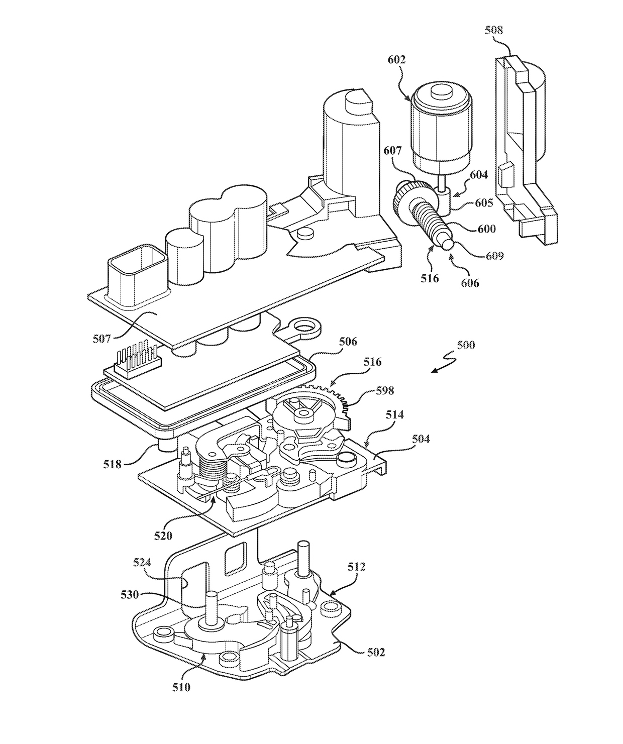
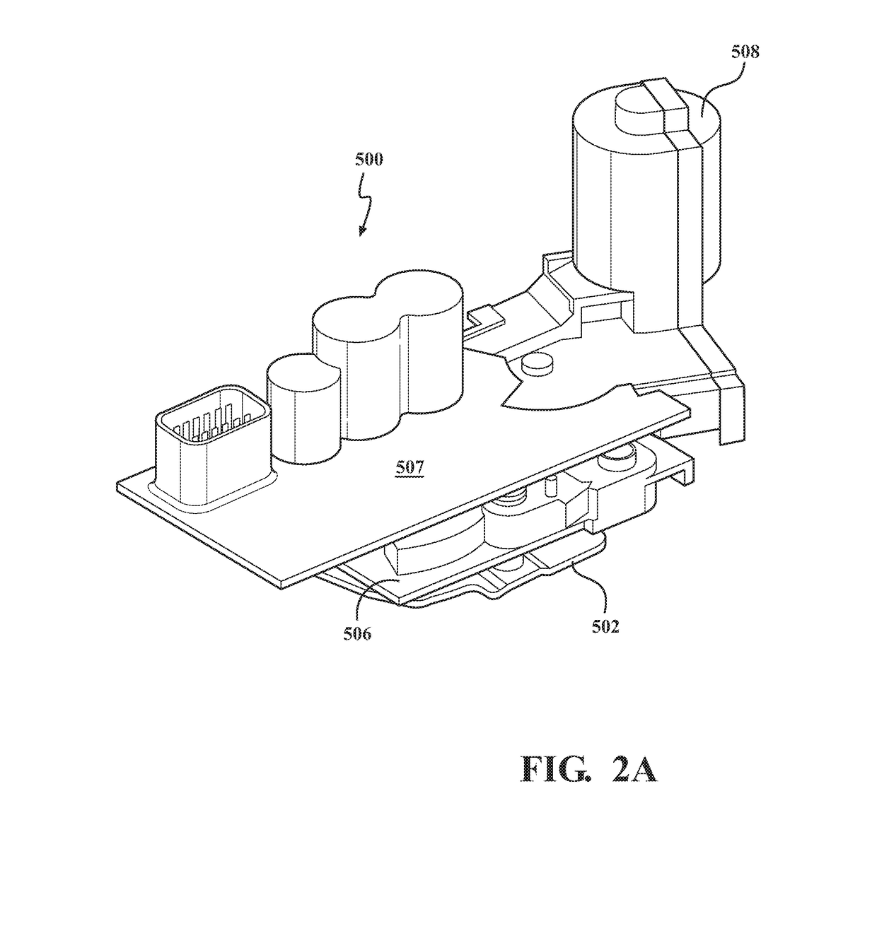
[0057]Various components of latch release mechanism 514 and actuation mechanism 516 are shown in FIGS. 7A-7C as being “built-up” on the components already described up through FIGS. 6A and 6B. Specifically, actuation mechanism 516 is shown to include an actuator gear 590 having a tubular boss segment 592 rotatably mounted on cinch lever pivot pin 560. Actuator gear 590 also includes a gear segment 594 having a drive aperture 596 within which gear link drive pin 562 is retained. As previously noted, gear link drive pin 562 is fixed to second end segment 552b of cinch lever 552. Based on this arrangement, actuator gear 590 and cinch lever 552 are coupled for common rotation about pivot point 560. Gear segment 594 of actuator gear 590 includes gear teeth 598 that are meshed, in this non-limiting example, with threads of a worm gear 600. A power-operated device, such as an electric motor 602, has a rotary output component configured to drive a first stage reduction gearset 604 which, in turn, drives a second stage reduction gearset 606. First stage gearset 604 includes a first worm gear 605 fixed for rotation with the rotary output of electric motor 602 and which is in constant mesh with a transfer gear 607 fixed for rotation with a drive shaft 609. As best seen from FIG. 2B, the rotary output of electric motor 602 is aligned to extend transversely to driveshaft 609. Second stage gearset 606 includes second worm gear 600 that is fixed for rotation with drive shaft 609 and, as noted, in constant mesh with gear teeth 598 on activator gear 590. This dual-stage double-worm arrangement provides a compact gear arrangement and, in the non-limiting configuration shown, provides a “square” or 90° orientation between the motor shaft and activator gear 590. In operation, bi-directional control of the rotation of the motor output component results in controlled bi-directional rotation of actuator gear 590 in concert with pivotal movement of cinch lever 552 about pivot axis 560.

Problems solved by technology

Because the seal loads exerted on the latching mechanism are increased, the forces required to release the latching mechanism are also increased which, in turn, impacts the size and power requirements of the electric actuator.

Method used


Image

  • One motor latch assembly with power cinch and power release having soft opening function
  • One motor latch assembly with power cinch and power release having soft opening function
  • One motor latch assembly with power cinch and power release having soft opening function

Examples


Embodiment Construction

[0048]Example embodiments will now be described more fully with reference to the accompanying drawings. To this end, the example embodiments are provided so that this disclosure will be thorough, and will fully convey its intended scope to those who are skilled in the art. Accordingly, numerous specific details are set forth such as examples of specific components, devices, and methods, to provide a thorough understanding of embodiments of the present disclosure. However, it will be apparent to those skilled in the art that specific details need not be employed, that example embodiments may be embodied in many different forms, and that neither should be construed to limit the scope of the present disclosure. In some example embodiments, well-known processes, well-known device structures, and well-known technologies are not described in detail.

[0049]In the following detailed description, the expression “power latch assembly” will be used to generally indicate any power-operated latch...


PUM


Abstract

A power latch assembly for a motor vehicle closure system configured to provide a power cinching feature and a power release feature. The power cinching feature is configured to retain the ratchet in a cinched striker capture position with the pawl engaged from the ratchet. The power release feature is configured to move the ratchet from its cinched striker capture position to a cinch release striker capture position for unloading the seals prior to release of the ratchet to its striker release position.

Description

CROSS-REFERENCE TO RELATED APPLICATIONS[0001]This application claims the benefit of U.S. Provisional Application No. 62 / 234,260, filed on Sep. 29, 2015. The entire disclosure of the above application is incorporated herein by reference.FIELD OF THE INVENTION[0002]The present disclosure relates generally to a closure latch for a vehicle closure panel and, more particularly, to a power latch assembly providing at least one of a power cinching feature and a power release feature having a soft opening function.BACKGROUND OF THE INVENTION[0003]This section provides background information related to the present disclosure which is not necessarily prior art.[0004]In view of increased consumer demand for motor vehicles equipped with advanced comfort and convenience features, many modern motor vehicles are now provided with passive entry systems to permit locking and release of closure panels (i.e., doors, tailgates, liftgates and decklids) without use of a traditional key-type entry system....

Claims


Application Information

Patent Timeline
Patent Type & Authority Applications(United States)
IPC IPC(8): E05B81/20E05B81/16E05B77/04E05B81/34E05B85/26E05B81/06E05B81/36
CPCE05B81/20E05B81/06E05B81/16E05B77/04E05B81/34E05B85/26E05B81/36E05B77/06E05B85/00
Inventor OTTINO, FRANCO GIOVANNICUMBO, FRANCESCOTAURASI, MARCOMARGHERITTI, ENRICO
Owner MAGNA CLOSURES SPA
Why Eureka
Try Eureka