
Baby gate

Inactive Publication Date: 2006-03-02
NITZ ALLEN S +1
View PDF14 Cites 13 Cited by
  • Summary
  • Abstract
  • Description
  • Claims
  • Application Information

AI Technical Summary

Benefits of technology

[0010] In an alternative embodiment, the gate further includes a caster wheel that is coupled with the bottom of the gate in order to facilitate pivotal movement of the gate and partially support the weight of the gate. By partially supporting the gate, the wheel reduces the load placed on the hinges.

Problems solved by technology

However, when at least one of the sides of the passageway is defined by a newel post, it is difficult to reliably wedge the feet against the newel post due to its rounded or curved side surface, and the fact that newel posts often become less stable with age allowing deflection of the post.
As a result, the post is not suitable for being used as a base against which the feet of a conventional gate may be wedged.

Method used


Image

  • Baby gate
  • Baby gate
  • Baby gate

Examples


first embodiment

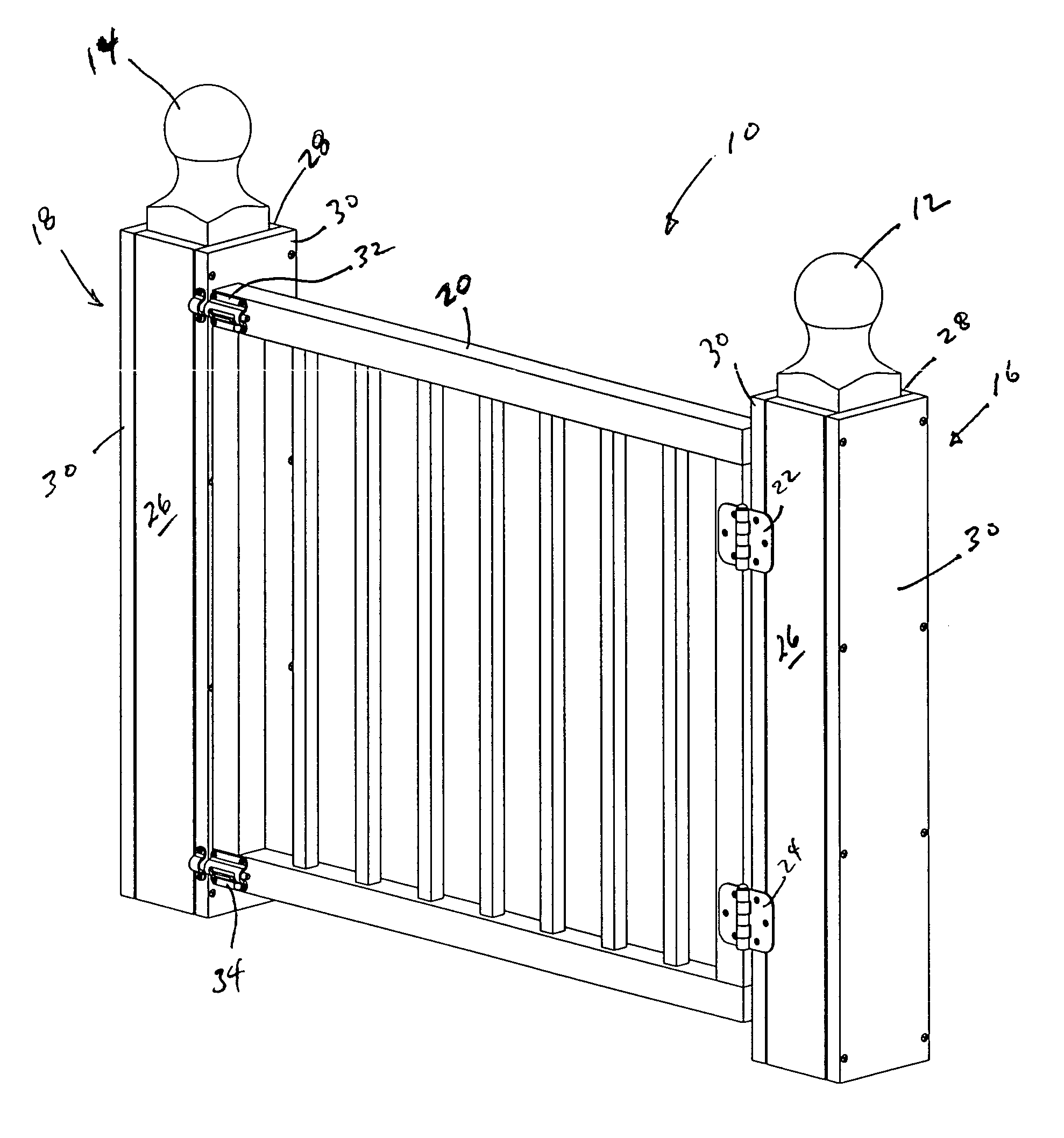
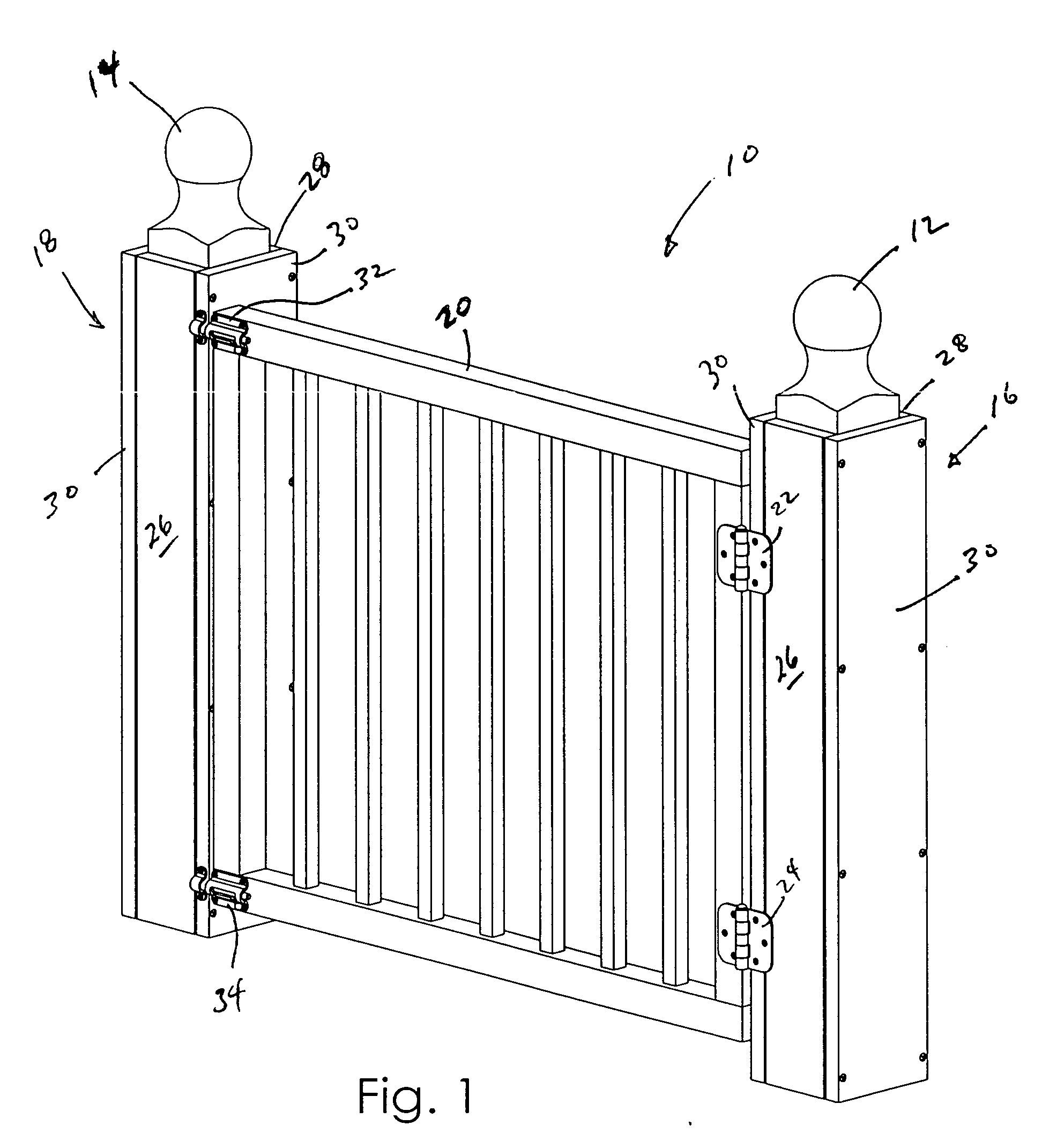
[0052] Referring now to the drawings, FIG. 1 depicts a passageway gate assembly 10 constructed in accordance with the present invention. The passageway gate assembly 10 is configured to be mounted in a passageway having opposed sides defined by a pair of newel posts 12, 14 for selectively opening and closing the passageway. Many such passageways exist at the base of or top of a staircase, a particular hazard for youngsters and pets.

[0053] The gate assembly 10 broadly includes a pair of mounting assemblies 16, 18, a gate 20 and a pair of hinges 22, 24 coupling the gate 20 to the first mounting assembly 16, and permitting pivotal movement of the gate 20 through an arc of 180° between a first, closed position and a second, open position. Each mounting assembly 16, 18 includes a mount face plate 26, a backing plate 28 and a plurality of fasteners 30 for mounting the face plate to one of the newel posts 12, 14. The combination of the face plate 26, the backing plate 28 and the fasteners ...

embodiment 88

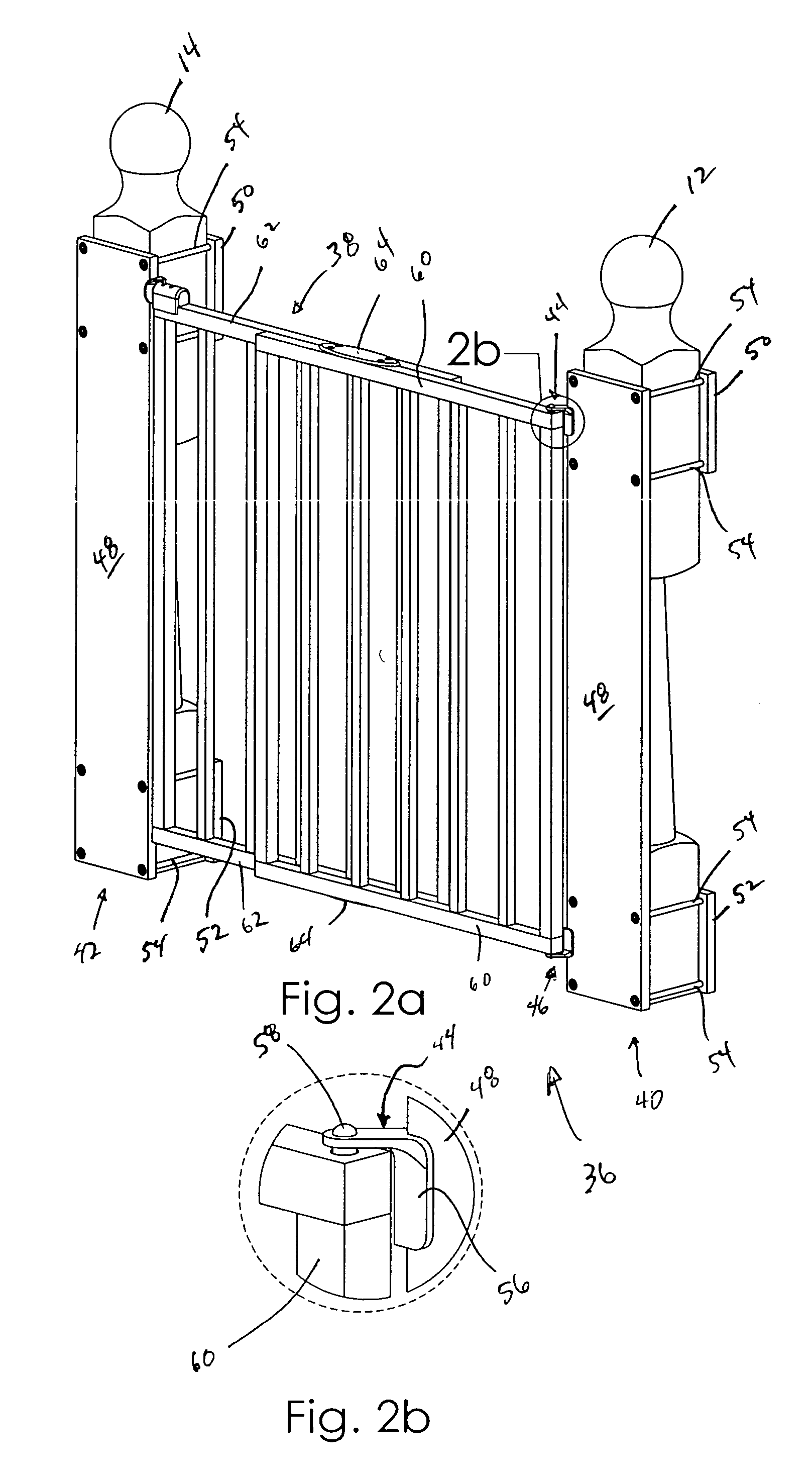
[0068]FIGS. 7a-d depict an alternative embodiment 88 of the present invention utilizing many of the same components as the preferred gate assembly 36. The gate assembly 88 incorporates a caster wheel assembly 90 coupled with the lower, distal portion of the gate 38. The wheel assembly 90 includes a rotatable wheel 92 and a pivoting strut 94 having a proximal end 96 received in an aperture formed in the gate 38. The strut 94 is movable between an extended position, shown in FIG. 7c, and a retracted position, shown in FIG. 7d. A spring 98 is provided in the aperture biasing the strut 94 toward the extended position.

[0069] In use, the wheel assembly 90 assists in supporting the weight of the gate 38. As a result, torsional forces exerted on the hinges 44, 46 are relatively reduced, extending the operational life of the hinges 44, 46.

[0070]FIGS. 11a-c illustrate various mounting assemblies. For example, FIG. 11a shows the mounting assembly 16, 18 used with the first embodiment 10 of th...


PUM


Abstract

A gate assembly for selectively opening and closing a passageway includes opposed sides defined by a pair of newel posts. The gate assembly includes a gate, first and second mounting assemblies and a pair of hinges. Each mounting assembly includes a mount face plate, a backing plate and a plurality of fasteners for mounting the face plate to one of the posts. The hinges define a hinge axis and couple the gate to the first mounting assembly face plate and permit pivotal movement of the gate about the hinge axis between first and second open positions and through a closed position through an arc of about 270°. The gate is substantially parallel to the face plate when in the closed position. A caster wheel is coupled with the bottom of the gate in order to facilitate pivotal movement of the gate and to inhibit undesired forces on the hinges.

Description

BACKGROUND OF THE INVENTION [0001] 1. Field of the Invention [0002] The present invention relates to a baby gate for selectively opening and closing a passageway. More particularly, the present invention relates to a novel structure enabling the gate to be set up in passageways previously not compatible with conventional baby gate devices. [0003] 2. Discussion of the Prior Art [0004] Many baby gate devices are known in the prior art that may be used to selectively open and close a passageway. A conventional baby gate is disclosed in U.S. Pat. No. 5,360,191 to Carson et al. (the '191 patent). The gate shown in the '191 patent includes a pair of gate panels coupled for longitudinal adjustment in order to permit the gate to fit in passageways of varying widths. The gate of the '191 patent utilizes feet on each of the adjustable panels to be wedged against the sides of the passageway in order to frictionally fit the gate in the passageway for closing the passageway. [0005] Such conventi...

Claims


Application Information

Patent Timeline
IPC IPC(8): E06B9/01
CPCE06B2009/002E06B9/04
Inventor NITZ, ALLEN S.NITZ, CAROLYN
Owner NITZ ALLEN S
Learn More