Catheter having a soft distal tip

Inactive Publication Date: 2008-01-03
ABBOTT INT ENTERPRISES LTD
View PDF19 Cites 35 Cited by
  • Summary
  • Abstract
  • Description
  • Claims
  • Application Information

AI Technical Summary

Benefits of technology

[0008] In one embodiment, a catheter having a soft distal tip is manufactured by disposing a soft sleeve over the distal end of a catheter tube and by extending a portion of the sleeve beyond the distal end of the catheter tube. The sleeve is essentially free of recesses before being coupled with the distal end of the catheter tube. The sleeve is finally affixed to the surface of the catheter tube, under temperature and pressure conditions that cause the ou

Problems solved by technology

A risk associated with catheters having an elevated degree of “pushability” is vessel injury or rupture .
Additionally, a stiff catheter tip may cause endothelial abrasion by rubbing against the wall of the vessel.
Unfort

Method used


Image

  • Catheter having a soft distal tip
  • Catheter having a soft distal tip
  • Catheter having a soft distal tip

Examples


second embodiment

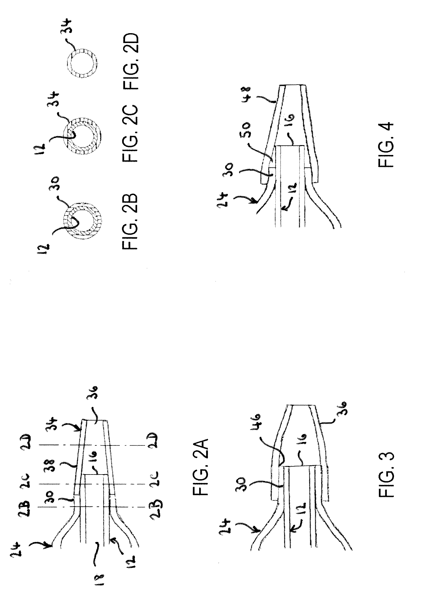
[0040]FIG. 3 illustrates the invention, in which sleeve 36 overlays both catheter tube 12 and distal neck 30. In this embodiment, distal neck 30 extends to the end of distal end 16, therefore, sleeve 36 is not welded to catheter tube 12, but rather is welded to distal neck 30, which in turn is welded to catheter tube 30. In this embodiment, sleeve 36 may be shaped in two main portions, a proximal portion having an essentially cylindrical shape that is welded to distal neck 30, and a distal portion having an essentially frusto-conical shape that extends beyond distal end 16. Alternatively, sleeve 36 may have an essentially frusto-conical configuration that is partially stretched to an essentially cylindrical shape in the area of contact with distal neck 30.

[0041] In order to achieve proper welding between sleeve 36 and distal neck 30, a mandrel and a shrink tube may employed as previously described. Also as previously described, one skilled in the art will recognize that the mandrel ...

third embodiment

[0042]FIG. 4 illustrates a third embodiment, in which sleeve 38 is partially overlapping distal neck 30, which does not extend as far as distal end 16. In this embodiment, the softening of sleeve 48 causes not only a smoothing of the transition between the outer surface of balloon 24 and sleeve 48, but also causes a partial or total filling of interstice 50 between the inner wall of sleeve 48 and the outer wall of catheter tube 12. As in the preceding embodiment, sleeve 48 may have a cylindrical or frusto-conical shape or a combination thereof, and may be stretchable from its original configuration to a modified configuration.

[0043]FIG. 5 illustrates a further embodiment of the invention, in which sleeve 52 is disposed distally of distal neck 30, and abuts the distal end of distal neck 30, similarly to the embodiment of FIG. 2A. When the proximal portion of sleeve 52 is welded against the outer wall of distal end 16, the combined action of the mechanical pressure exercised on sleeve...


PUM

PropertyMeasurementUnit
Temperatureaaaaaaaaaa
Thicknessaaaaaaaaaa
Pressureaaaaaaaaaa

Abstract

The present invention relates to a catheter having a soft distal tip that can be manufactured at lower cost than catheters in the prior art. In one embodiment, the catheter is produced by coupling a soft sleeve to the distal end of a catheter tube. The sleeve may affixed to the catheter tube under temperature and pressure conditions that cause the proximal end of the sleeve to taper against the outer surface of the catheter tube, avoiding or minimizing discontinuities in the insertion profile of the catheter, and that also cause the inner wall of the sleeve to taper against the distal end of the catheter tube, avoiding or minimizing discontinuities in the lumen of the catheter.

Description

CROSS-REFERENCE TO RELATED APPLICATIONS [0001] The present application is a continuation-in-part of U.S. application Ser. No. 10 / 296,252, filed on Nov. 21, 2002, which claims priority to PCT application no. PCT / EP01 / 05893, filed on May 22, 2001, which claims priority to German application no. 200092049, filed on May 22, 2000, the entireties of which are incorporated herein by reference. The present application is also the continuation-in-part of U.S. application Ser. No. 11 / 335,931, filed on Jan. 20, 2006, which claims priority to provisional application Ser. No. 60 / 646,118, filed on Jan. 21, 2005, the entireties of which are incorporated herein by reference.FIELD OF THE INVENTION [0002] The present invention relates to a catheter having a soft distal tip and to methods of manufacture thereof. More particularly, the present invention relates to a catheter having a soft distal tip and to methods of manufacture, in which the soft distal tip is formed by affixing a soft sleeve to the d...

Claims


Application Information

Patent Timeline
IPC IPC(8): A61M25/10A61F2/958
CPCA61F2/958A61M25/0069A61M25/10A61M25/1006Y10T29/49826A61M25/104A61M2025/0081A61M2025/1093A61M25/1027
Inventor JEFFREY, ANDREWBALFE, LOUISECOFFEY, LORCANZUCKER, ARIKUNZICKER, KAYDZAKULA, ZDRAVKICAJOERGENSEN, IBVON OEPEN, RANDOLF
Owner ABBOTT INT ENTERPRISES LTD
Why Eureka
Try Eureka