Image taking apparatus

Inactive Publication Date: 2008-01-10
FUJIFILM CORP
View PDF3 Cites 8 Cited by
  • Summary
  • Abstract
  • Description
  • Claims
  • Application Information

AI Technical Summary

Benefits of technology

[0008]The present invention has been made in view of the above circumstances and provides an image taking apparatus provided with a lens driving unit that drives a zoom lens and a focus lens independently, using a single driving shaft while avoiding the conventional complicated structure.
[0012]Namely, the present invention can avoid the complicated structure of the conventional lens driving unit and realize the lens driving unit having a simple structure in which the single shaft to which two coils are magnetically connected is disposed parallel to an optical axis. In addition, such a simple structure eliminates the need of a mechanical part that connects the shaft with the lens holding frame. Thus, power supplied from the zoom driving section and the focusing section is efficiently used without loss when driving lenses.
[0013]As described above, the present invention can realize the image taking apparatus having the lens driving unit that drives a zoom lens and a focus lens separately using a single driving shaft while avoiding the conventional complicated structure.
[0018]If the image taking apparatus is provided with the magnet, the lens holding frames are biased in the direction perpendicular to the optical axis irrespective of whether the coils are energized or not. Thus, by controlling magnetic force of the magnet, each of the lens holding frames can be always held at a desirable position so as not to contact the shaft. Consequently, it becomes possible to precisely adjust positioning of the focus lens and zoom lens and to perform position control after the positioning of the lenses when the first coil and / or the second coil are energized.
[0019]As described above, the present invention can realize the image taking apparatus having the lens driving unit that drives a zoom lens and a focus lens independently using a single driving shaft while avoiding the conventional complicated structure.

Problems solved by technology

However, according to the above-mentioned technique, the driving shaft should be coaxial, and / or a switching mechanism such as a clutch must be provided at a part of the driving shaft, which makes the structure of the lens driving unit complicated.

Method used


Image

  • Image taking apparatus
  • Image taking apparatus
  • Image taking apparatus

Examples


Embodiment Construction

[0029]Embodiment(s) of the present invention will be described with reference to the accompanying drawings.

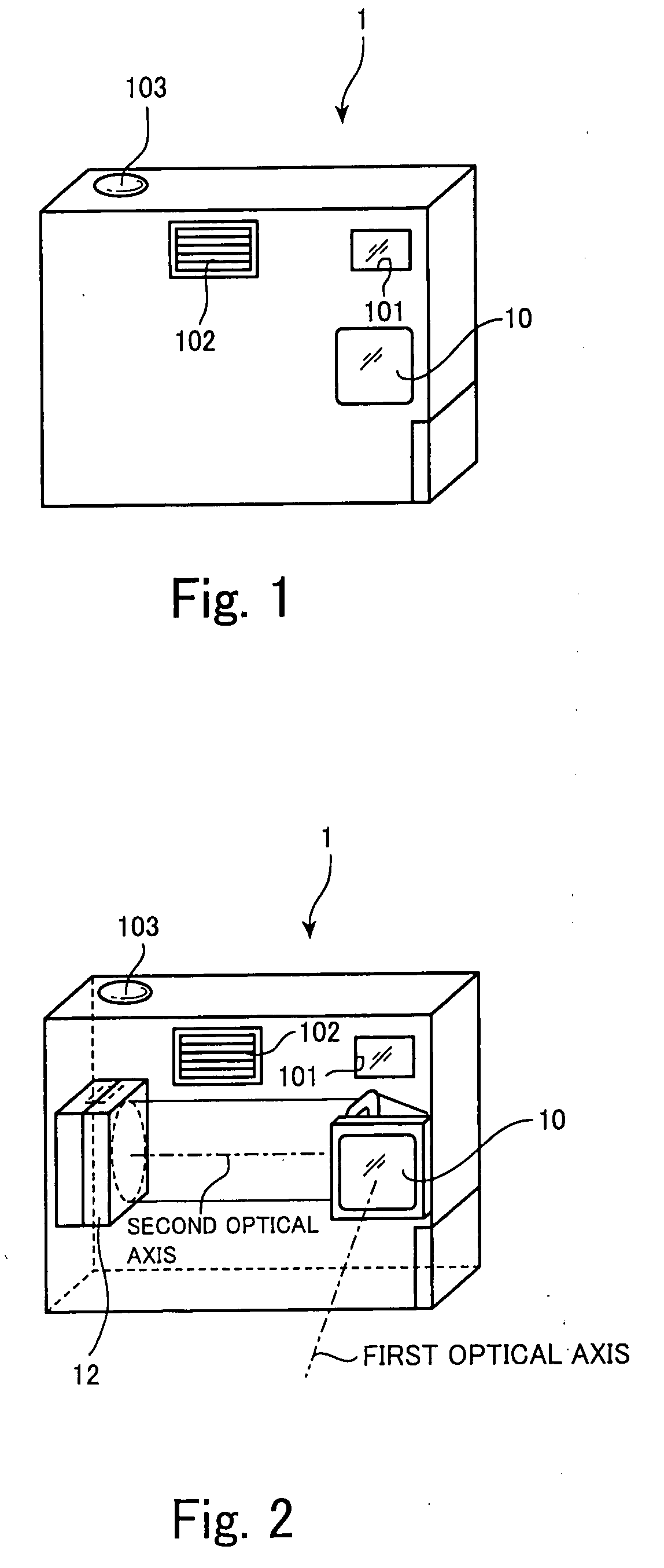
[0030]FIGS. 1 and 2 are schematic diagrams illustrating a configuration of a digital camera 1 according to an embodiment of the present invention. More specifically, FIG. 1 shows an external view of the digital camera 1 and FIG. 2 shows how a refractive optical system is accommodated inside the digital camera 1.

[0031]The digital camera 1 shown in FIG. 1 includes: an image taking lens 10 partly shown at the right side of an approximately center of the body of the digital camera 1; a fill flash window 101 disposed above the image taking lens 10 from which a flash is emitted toward an object; a finder 102 disposed beside the fill flash window 101; and a release button 103 disposed on a top surface of the body of the digital camera 1.

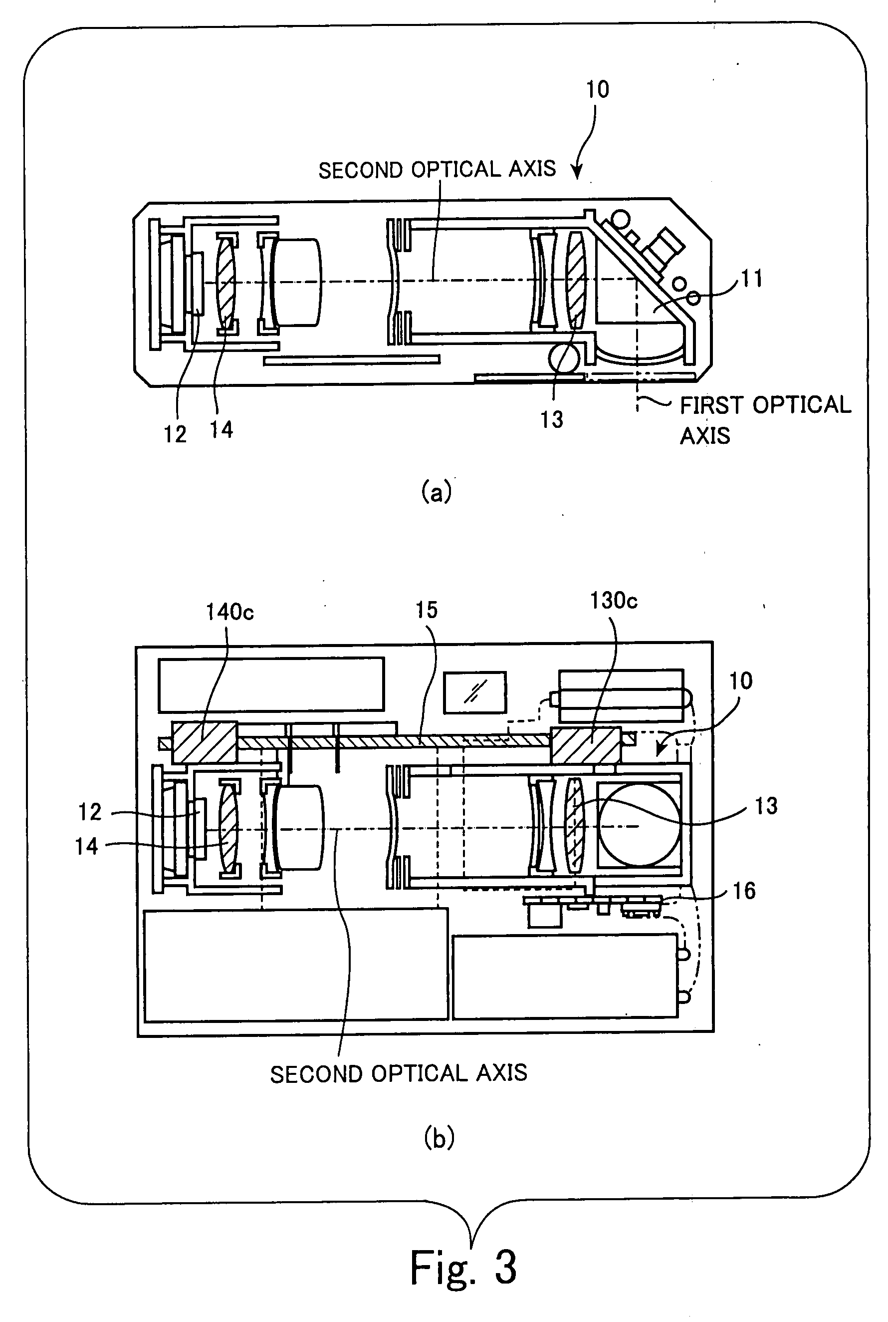
[0032]As shown in FIG. 2, the refractive optical system represented by the image taking lens 10 is accommodated in the digital camera 1. It should be ...


PUM


Abstract

An image taking apparatus is provided with a lens driving unit that includes a magnetic shaft in which the S pole and the N pole are alternately aligned in a longitudinal direction of the shaft. The lens driving unit also includes a first lens holding frame that holds a first lens and has a first coil, and a second lens holding frame that holds a second lens and has a second coil. The magnetic shaft is inserted in the first and second coils, so that each of the first and second coils form a linear motor in cooperation with the magnetic shaft.

Description

BACKGROUND OF THE INVENTION[0001]1. Field of the Invention[0002]The present invention relates to an image taking apparatus that obtains an image of an object through an image taking optical system and generates image data representing the object.[0003]2. Description of the Related Art[0004]Generally, an image taking optical system provided in an image taking apparatus includes a focus lens and a zoom lens that are required to be moved along an optical axis. Moving such lenses independently requires lens driving units each with a motor and a driving shaft that are provided for the respective lenses, resulting in the enlarged lens barrel in which the lens driving units are incorporated.[0005]In order to miniaturize the lens barrel, there have been proposed a technique in which two driving shafts provided in the respective two lens driving units are integrated into one driving shaft so as to be used in common (see, for example, Japanese Patent Application Laid Open Nos. 8-292358, 2002-...

Claims


Application Information

Patent Timeline
IPC IPC(8): G02B7/04
CPCG02B7/102
Inventor OTAKA, HIROYUKI
Owner FUJIFILM CORP
Why Eureka
Try Eureka