Wireless receiving apparatus and method

a receiving apparatus and wireless technology, applied in the field of wireless receiving apparatus and method, can solve the problems of inability to generate accurate sine waves and conventional wireless receiving apparatuses cannot correct errors

Inactive Publication Date: 2008-01-10
KK TOSHIBA +1
View PDF0 Cites 70 Cited by
  • Summary
  • Abstract
  • Description
  • Claims
  • Application Information

AI Technical Summary

Problems solved by technology

In general, it is difficult to generate accurate sine waves, which may well cause frequency offsets.
However, the conventional wireless receiving apparatuses cannot correct errors that occur during channel response estimation because of phase errors.

Method used


Image

  • Wireless receiving apparatus and method
  • Wireless receiving apparatus and method
  • Wireless receiving apparatus and method

Examples


first embodiment

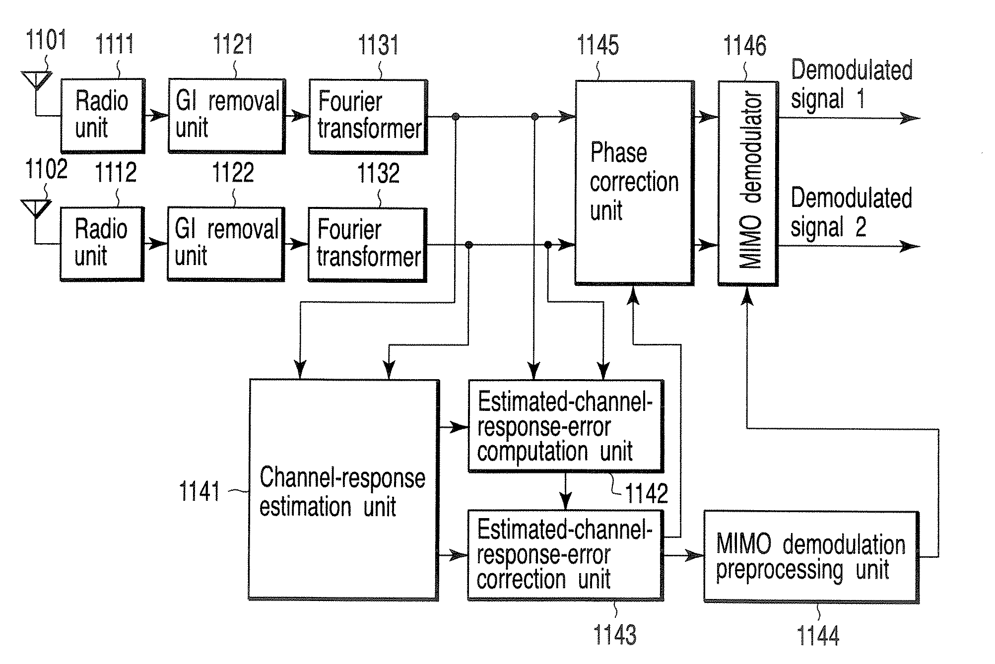
[0064]Referring first to FIG. 11, the configuration of the wireless receiving apparatus of a first embodiment will be described. FIG. 11 shows a configuration example of the wireless receiving apparatus according to the first embodiment, in which the number of streams to be multiplexed is 2, and the number of receiving antennas is also 2.

[0065]The wireless receiving apparatus of the first embodiment comprises receiving antennas 1101 and 1102, radio units 1111 and 1112, GI removal units 1121 and 1122, Fourier transformers 1131 and 1132, channel-response estimation unit 1141, estimated-channel-response-error computation unit 1142, estimated-channel-response-error correction unit 1143, phase correction unit 1145, MIMO demodulation preprocessing unit 1144 and MIMO demodulator 1146.

[0066]The radio units 1111 and 1112 perform radio processing through the receiving antennas 1101 and 1102, respectively, thereby converting radio frequency signals into digital signals. The receiving antennas ...

second embodiment

[0168]A wireless receiving apparatus according to a second embodiment has the same configuration as that of the first embodiment shown in FIGS. 11 or 13, and is similar to the latter in that an estimated channel-response error, caused by the frequency offset between the transmission apparatus and wireless receiving apparatus and phase noise resulting therefrom, is corrected using pilot subcarriers.

[0169]The second embodiment differs from the first embodiment in the scheme of computing a weight in units of pilot subcarriers to acquire an estimated channel-response error. Specifically, they employ different weight computation methods for the estimated-channel-response-error computation unit 1142. In the first embodiment, a weight is computed in units of pilot subcarriers using the equations (42) to (45). This method involves no problems if the signal-to-noise ratio (SNR) is high, and signal power is sufficiently higher than noise power. However, if SNR is low, noise may be emphasized ...

third embodiment

[0193]A wireless receiving apparatus according to a third embodiment has the same configuration as that of the first or second embodiment shown in FIGS. 11 or 13, and is similar to the first or second embodiment in that an estimated channel-response error, caused by the frequency offset between the transmission apparatus and wireless receiving apparatus and phase noise resulting therefrom, is corrected using pilot subcarriers.

[0194]The third embodiment differs from the first or second embodiment in the scheme of computing a weight in units of pilot subcarriers to acquire an estimated channel-response error. Specifically, they employ different weight computation methods for the estimated-channel-response-error computation unit 1142.

[0195]In the first and second embodiments, a weight is computed in units of pilot subcarriers using the equations (42) to (45) and the equations (80) to (83), respectively. These methods utilize common inverse matrix G−1 for all subcarriers, and hence redu...


PUM


Abstract

A wireless receiving apparatus includes antennas, a receiving unit configured to receive multiple input multiple output-orthogonal frequency division multiplexing (MIMO-OFDM) signals via the antennas, an estimation unit configured to estimate channel response values of subcarriers included in the MIMO-OFDM signals, a first computation unit configured to compute an estimated channel-response error common to the subcarriers based on the estimated channel response values, a response correction unit configured to correct the estimated channel response values using the estimated channel-response error, and a second computation unit configured to perform preprocessing for demodulating the MIMO-OFDM signals, using the corrected channel response values.

Description

CROSS-REFERENCE TO RELATED APPLICATIONS[0001]This application is based upon and claims the benefit of priority from prior Japanese Patent Application No. 2006-185876, filed Jul. 5, 2006, the entire contents of which are incorporated herein by reference.BACKGROUND OF THE INVENTION[0002]1. Field of the Invention[0003]The present invention relates to a wireless receiving apparatus and method for correcting an estimated channel response value using signals received through a plurality of subcarriers, which employ Multiple Input Multiple Output-Orthogonal Frequency Division Multiplexing (MIMO-OFDM) for communication using a plurality of transmission / receiving antennas.[0004]2. Description of the Related Art[0005]MIMO transmission for distributing a transmission signal to a plurality of radio units and simultaneously transmitting a plurality of signals, output from the radio units, through a plurality of transmission antennas, using a single frequency has been proposed as a technique for ...

Claims


Application Information

Patent Timeline
Patent Type & Authority Applications(United States)
IPC IPC(8): H04L1/02H04J99/00
CPCH04L25/0204H04L25/024H04L25/0228H04L25/022
Inventor TANABE, YASUHIKO
Owner KK TOSHIBA
Why Eureka
Try Eureka