
Draft sill wear liner

a technology of draft gear and draft sill, which is applied in the direction of draw gear, rail components, railway coupling accessories, etc., can solve the problems of affecting the coupler of the awaiting car. , to achieve the effect of reducing maintenance and minimizing damage to the draft sill

Active Publication Date: 2008-01-17
AMSTED RAIL CO INC
View PDF6 Cites 19 Cited by
  • Summary
  • Abstract
  • Description
  • Claims
  • Application Information

AI Technical Summary

Benefits of technology

The present invention provides a solution for protecting the coupling assembly of rail cars from damage caused by train action and yard impact events. The invention includes a draft sill, draft gear assembly, and draft sill liner. The liner is placed between the draft gear and the draft sill to hold them in spaced relation to each other and protect the draft sill from wear and damage. The liner can be used in various types of train car coupling assemblies and is adaptable to different draft gear designs. The technical effect of the invention is to minimize damage to the draft sill and reduce maintenance costs.

Problems solved by technology

Excess wear on the inside of the sidewalls of the draft sills causes premature failure or increased maintenance.
Yard impact events include “humping” of the individual cars to build the train in the yard; in humping, a car is pushed over a hump in the track in the yard, released and allowed to roll down the incline of the hump toward an awaiting car; during humping, the released cars can reach speeds of 4-10 mph and can severely impact the coupler of the awaiting car.
Friction between the draft gear and the draft sill is not acceptable as it causes damage to the draft sill that is harder and more expensive to repair or replace.
As a result of the slack being progressively taken up, the speed differences between the railcars increases as the slack at each coupler pair is taken up, with a resultant increase in buff and draft impacts on the couplers.
The slack in the last coupler pair is taken up very rapidly and the last two cars are subjected to a very large impact capable of injuring the lading or the car.
The impact causes the resilient members of the draft gear to expand or compress creating a possible frictional engagement between parts of the draft gear and the sidewalls of the draft sill causing damage.
The draft sill may still be susceptible to failure due to wear between the draft gear and the draft gear because of less steel used to reduce weight.
The steel housing adds to the weight of the railcar and may rub against the draft sill.
Those employing elastomer springs or steel springs or plates for resilient absorption of the impact of buff and draft events may cause rubbing and friction between the springs and the sill.
The friction causes heat and fatigue of the draft sill that will lead to premature failure of the draft sill or increased maintenance.

Method used


Image

  • Draft sill wear liner
  • Draft sill wear liner
  • Draft sill wear liner

Examples


Embodiment Construction

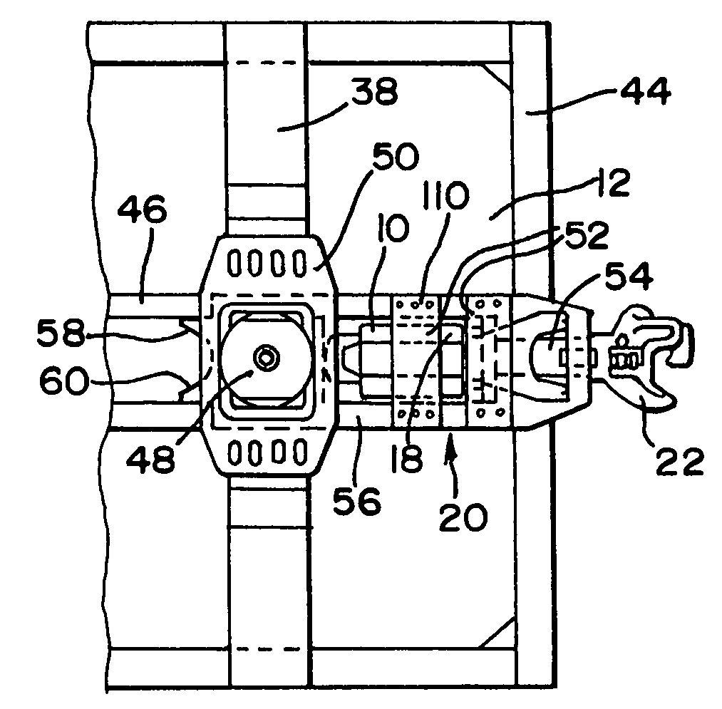
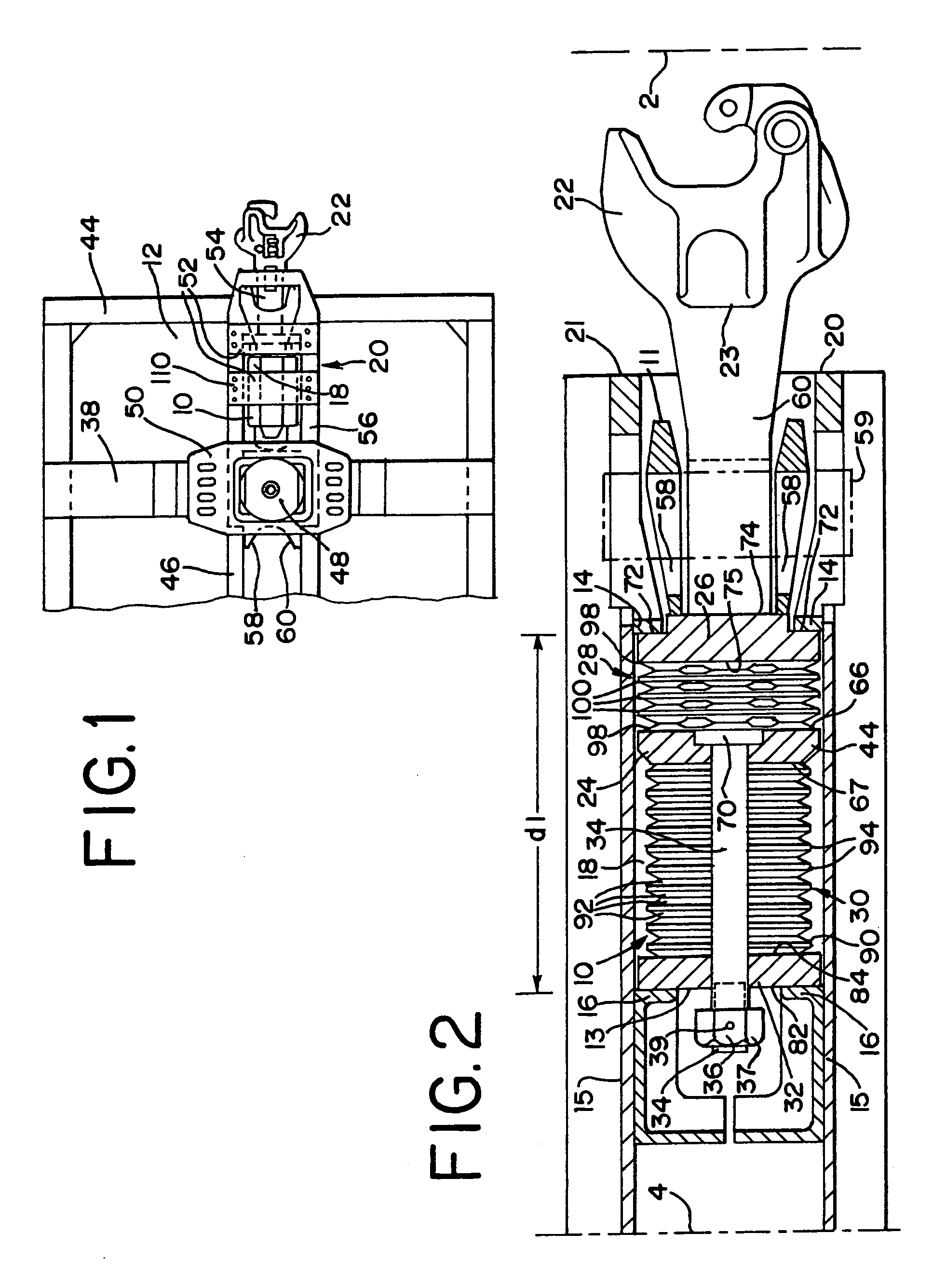
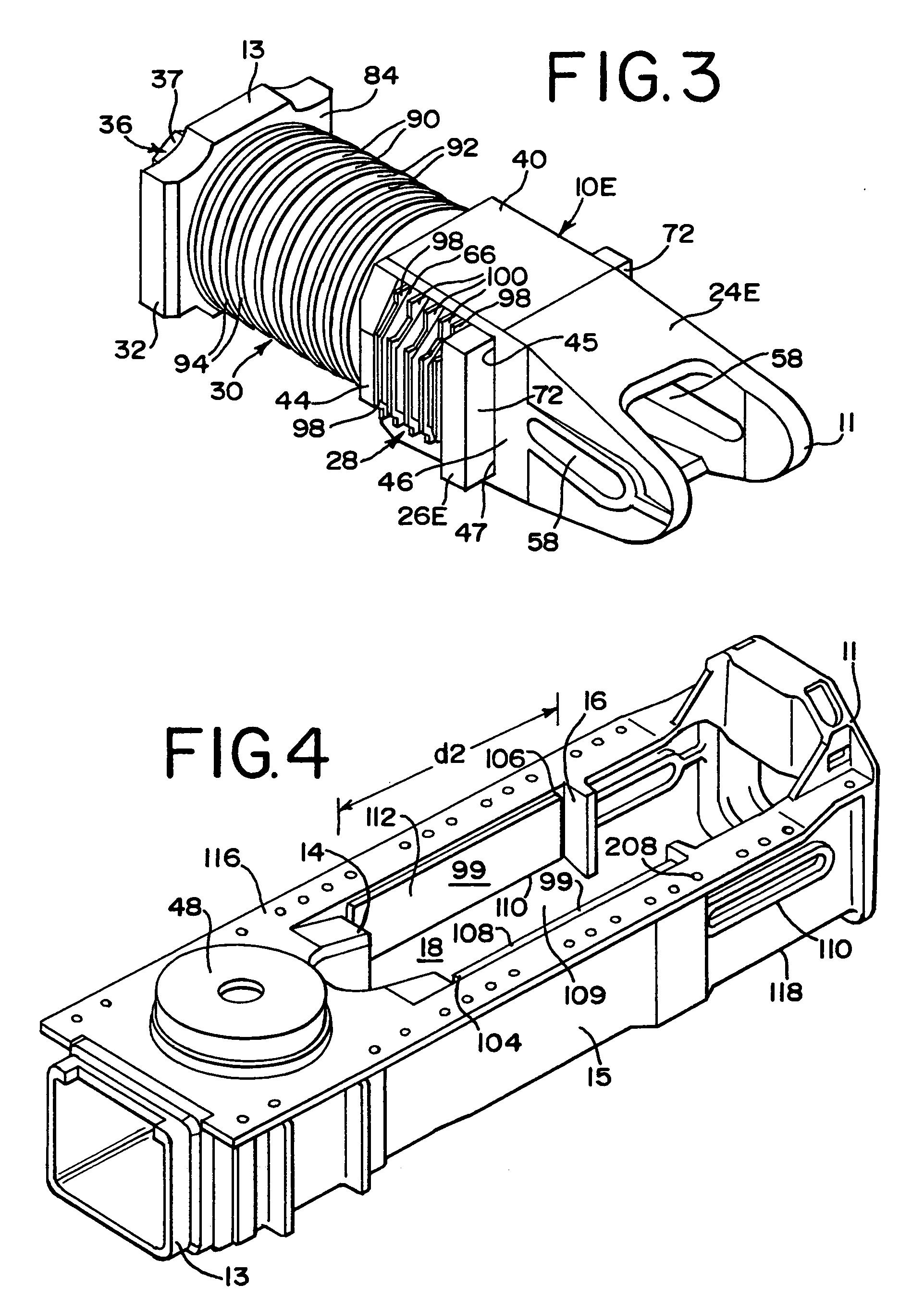
[0027]Referring to FIG. 1, a typical cast draft sill 20 is shown mounted to the structure of a railroad freight car 12. In the mounted position, the cast draft sill 20 is secured to an end sill 44, the body bolster 38, and a center sill 46. The draft sill 20 typically has a top wall that is welded or otherwise affixed to a shear plate that is connected to the bottom of the railway car. The railway car center sill 46 typically runs the length of the car 12 (but on some cars may extend around the periphery of the car depending on car configuration). Buff and draft forces are thus generally transferred between the draft sill 20 structure, the car truck 12 and the center sill 46 of the car 12. The draft sill 20 has a draft gear 10 mounted within a draft gear pocket 14 and coupler 16 shank 54 extended through the outboard end 21 thereof. A center filler plate 48 is mounted in the center filler plate pocket of the cast draft sill 20, such as by welding, or may be integrally formed. Center...


PUM


Abstract

A liner for use in a draft sill to protect the sill from damage and wear caused by draft gear movement. The draft gear is attached to a coupling to transmit moving forces from the coupling to the car causing. The draft gear is isolated from the side walls of the draft sill by the liner to reduce wear on the draft sill as the draft gear absorbs and cushions impacts from the buff and drag events. These impacts may cause the followers, yoke and resilient members move toward the side walls and contact the liner disposed between the draft gear and the draft sill for protecting the side walls from damage and wear.

Description

BACKGROUND OF THE INVENTION[0001]The present invention relates to railcar coupling systems, and more particularly to rail car connection assemblies comprising draft gears and draft sills and couplers in railcars.[0002]Rail cars are interconnected by couplers attached to draft gear assemblies at the ends of adjoining railroad freight cars. The draft gear assembly is disposed in the draft sills at the ends of the freight cars. The draft sills are commonly cast or fabricated sills that are mounted at the ends of the center sills of the railcar. The sidewalls of the draft sill each have a front stop and a rear stop, with a draft gear pocket between the stops. The draft gear assembly is received in the draft gear pocket. The draft rear is connected to the coupler and adapted to transfer motion to the car while absorbing impacts from train action events. A front resilient member cushions the coupling from impacts caused by draft events where the coupling is pulled away from the car. A rea...

Claims


Application Information

Patent Timeline
Patent Type & Authority Applications(United States)
IPC IPC(8): B61G7/00
CPCB61G9/24
Inventor BROUGH, STEVEMALINOWSKI, W. TOMASZ
Owner AMSTED RAIL CO INC
Learn More