Screw and rod fixation assembly and device

a technology of fixing assembly and screw, which is applied in the direction of ligaments, prostheses, osteosynthesis devices, etc., can solve the problems of affecting the movement of the screw can be detrimental to the healing process of the spine, and the patient cannot be directly in line with three or more implants, etc., to achieve the effect of reducing x-ray obstruction

Active Publication Date: 2008-01-17
AESCULAP IMPLANT SYST
View PDF99 Cites 131 Cited by
  • Summary
  • Abstract
  • Description
  • Claims
  • Application Information

AI Technical Summary

Problems solved by technology

The spine anatomy, however, rarely allows for three or more implants to be directly in line.
Any movement of the screw can be detrimental towards the healing process of the spine.
Further, additional damage can occur if there is movement of the screw once it has been fixed to the vertebrae.
Typically, the more complex the locking mechanism, larger components are needed and manufacturing costs are expensive.
Locking and achieving strong hold values become more difficult with more parts.
Bulky components can cause soft tissue irritation, as well as compromise the facet joints at the end of a fusion.
Soft tissue irritation resulting from extensions of implants is a common occurrence.
For example, implants can be too thick to be sufficiently covered within the muscle tissue.

Method used


Image

  • Screw and rod fixation assembly and device
  • Screw and rod fixation assembly and device
  • Screw and rod fixation assembly and device

Examples


Embodiment Construction

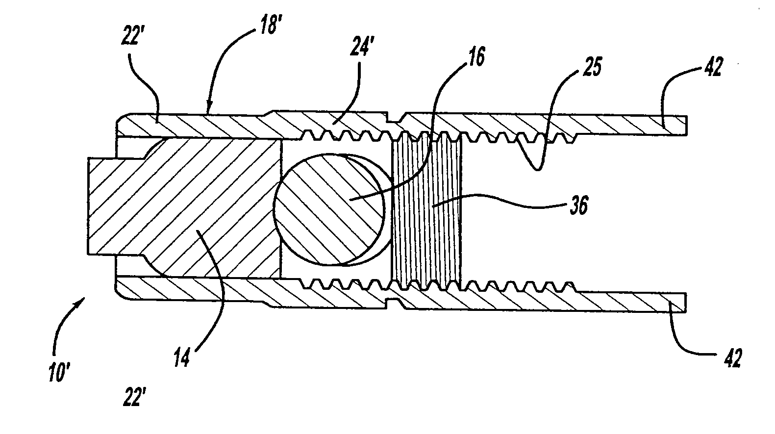
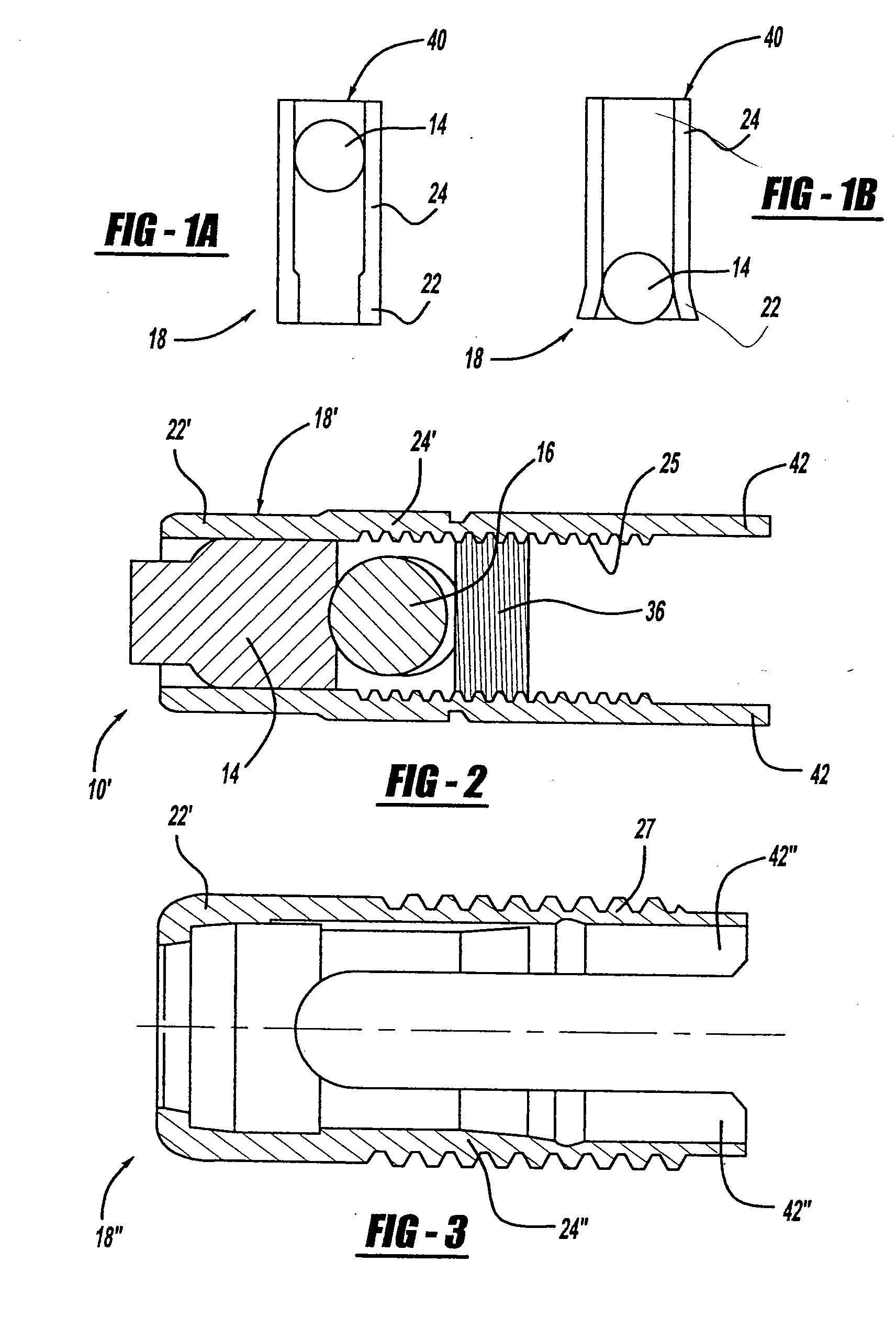
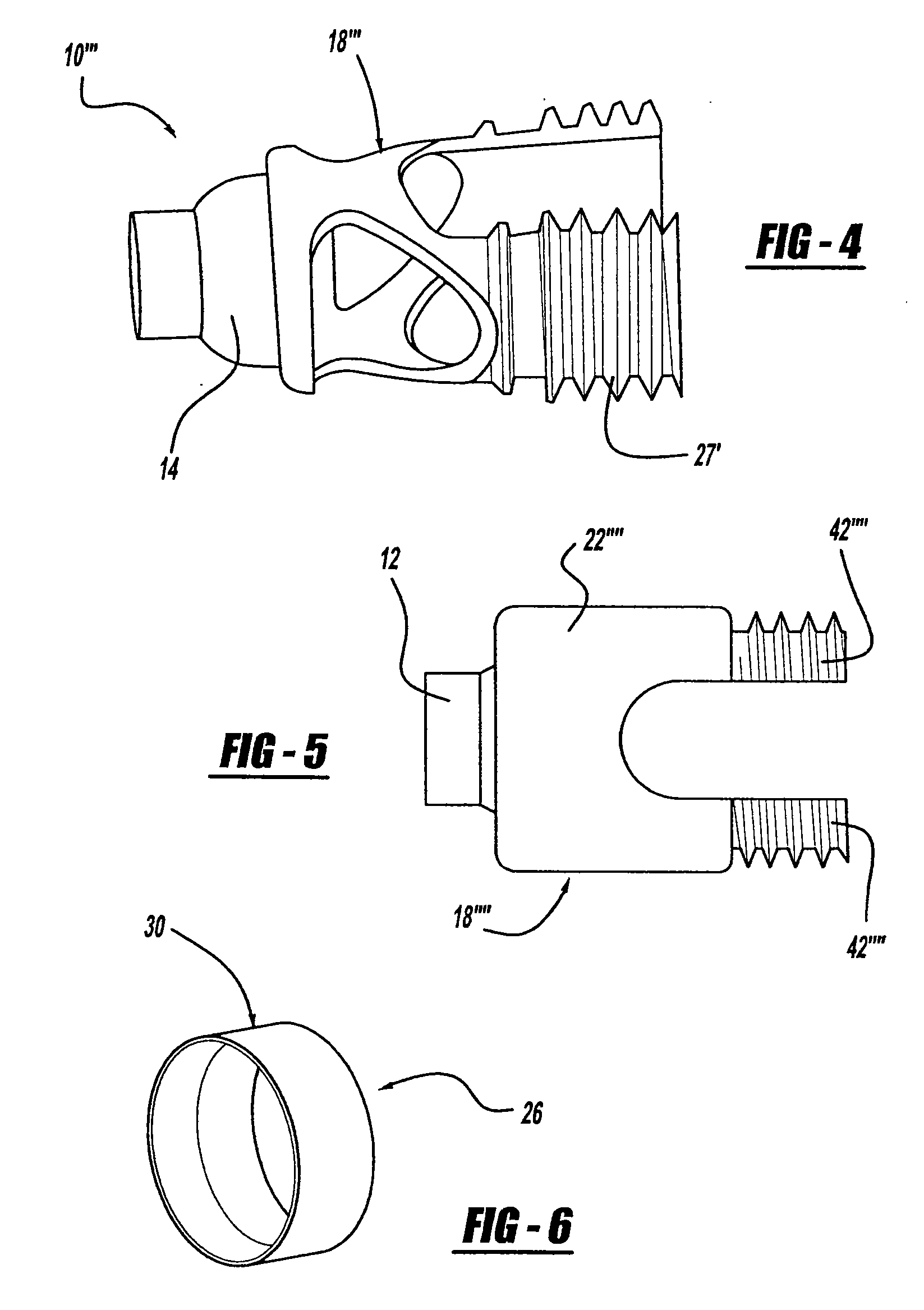
[0039] A screw and rod fixation assembly constructed in accordance with the present invention is generally indicated by 10 in the Figures. Generally, the screw and rod fixation assembly 10 fixes and / or locks a screw, a rod, or both. Additionally, the screw and rod fixation assembly 10 includes various components in different combinations. For instance, the screw and rod fixation assembly 10 can include any, all, or combinations of a screw, fixing mechanism, substantially annular ring, rod seating mechanism, and locking mechanism.

[0040] The present invention provides for locking of a screw head without any manipulation of the fixing mechanism thereof. The fixing mechanism inherently grips the screw head rigidly, preventing movement of the screw head that can occur because of vertebrae movement, without application of force or manipulation of the fixing mechanism as required to ensure the fixed gripping. Rather, entry of the screw head into the locking or gripping portion of the fixi...


PUM


Abstract

The present invention provides for a screw and rod fixation assembly for fixing a screw and, optionally, a rod. The screw and rod fixation assembly includes a screw, fixing mechanism, a substantially annular ring, rod seating mechanism, and locking mechanism. The present invention also provides for a fixing mechanism for fixing a screw, wherein the fixing mechanism further includes an inner surface wall having a gripping portion and a non-gripping portion. Further, the present invention provides for a substantially annular ring for guiding and providing mechanical and frictional force to a screw head. Additionally, the present invention provides for a rod seating mechanism operatively engaged to the screw head and including at least one flexible portion capable of being compressed against a portion of a rod therein. Finally, the present invention provides for a locking mechanism for engaging the rod and the rod seating mechanism. The locking mechanism includes a deflecting mechanism for deflecting the at least one flexible portion of the rod seating mechanism against and around the rod as the locking mechanism further engages the at least one flexible portion of the rod seating mechanism.

Description

BACKGROUND OF THE INVENTION [0001] 1. Technical Field [0002] The present invention relates to fixation assemblies. More particularly, the present invention relates to screw fixation assemblies for use with bone fixation systems. [0003] 2. Background Art [0004] Several techniques and systems have been developed for correcting and stabilizing the spine and for facilitating fusion at various levels of the spine. Stabilization of the spine for various conditions, including degenerative disk disease, scoliosis, spondylolisthesis, and spinal stenosis, often require attaching implants to the spine and then securing the implants to spinal rods. Such spinal fixation devices can immobilize the vertebrae of the spine and can alter the alignment of the spine over a large number of vertebrae by connecting at least one elongate rod to the sequence of selected vertebrae. These rods can span a large number of vertebrae, such as three or four. The spine anatomy, however, rarely allows for three or m...

Claims


Application Information

Patent Timeline
Patent Type & Authority Applications(United States)
IPC IPC(8): A61B17/58A61B17/70
CPCA61B17/7037A61B17/7032
Inventor RICHELSOPH, MARC
Owner AESCULAP IMPLANT SYST
Why Eureka
Try Eureka