Sterilization system and method suitable for use in association with filler devices

a filler device and sterilization system technology, applied in the direction of liquid handling, closure using stoppers, transportation and packaging, etc., can solve the problems of high temperature required to effectively sterilize a surface, inability to reduce the time needed to effect proper sterilization, and high dwell time associated with effective sterilization. achieve the effect of preventing the release of hydrogen peroxid

Inactive Publication Date: 2008-01-24
SCHOLLE CORP
View PDF14 Cites 27 Cited by
  • Summary
  • Abstract
  • Description
  • Claims
  • Application Information

AI Technical Summary

Benefits of technology

[0015]In another such preferred embodiment, the translating assembly further includes a recovery assembly surrounding at least a portion of the metering means, to, in turn, preclude the undesirable release of hydrogen peroxide from the injector upon movement thereof by the translating assembly.

Problems solved by technology

While such a system does not require any chemicals and the sterilant is widely available, the temperatures required to effectively sterilize a surface, and the dwell time associated with an effective sterilization can often be excessive.
Advantageously, such a procedure can be accomplished with lower temperatures, however, the time needed to effect proper sterilization is often not reduced as compared to the utilization of steam alone.
Additionally, such systems may expose the operator to unacceptable levels of hydrogen peroxide.
Such a system generally requires tight controls and can be hazardous to operators which may be exposed to unsuitable levels of hydrogen peroxide.

Method used


Image

  • Sterilization system and method suitable for use in association with filler devices
  • Sterilization system and method suitable for use in association with filler devices
  • Sterilization system and method suitable for use in association with filler devices

Examples


Embodiment Construction

[0036]While this invention is susceptible of embodiment in many different forms, there is shown in the drawings and described herein in detail a specific embodiment with the understanding that the present disclosure is to be considered as an exemplification of the principles of the invention and is not intended to limit the invention to the embodiment illustrated.

[0037]It will be understood that like or analogous elements and / or components, referred to herein, may be identified throughout the drawings by like reference characters. In addition, it will be understood that the drawings are merely schematic representations of the invention, and some of the components may have been distorted from actual scale for purposes of pictorial clarity.

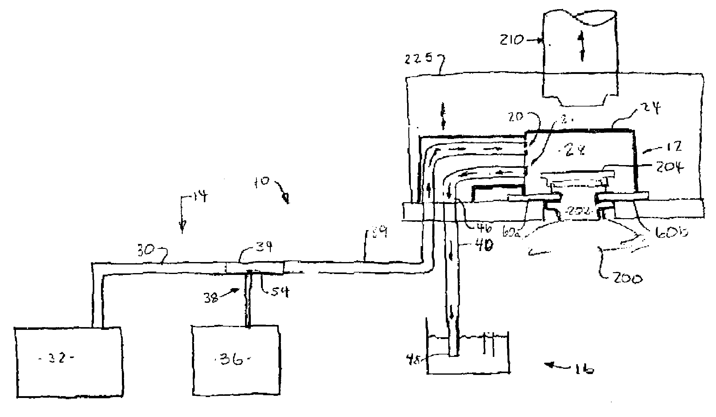
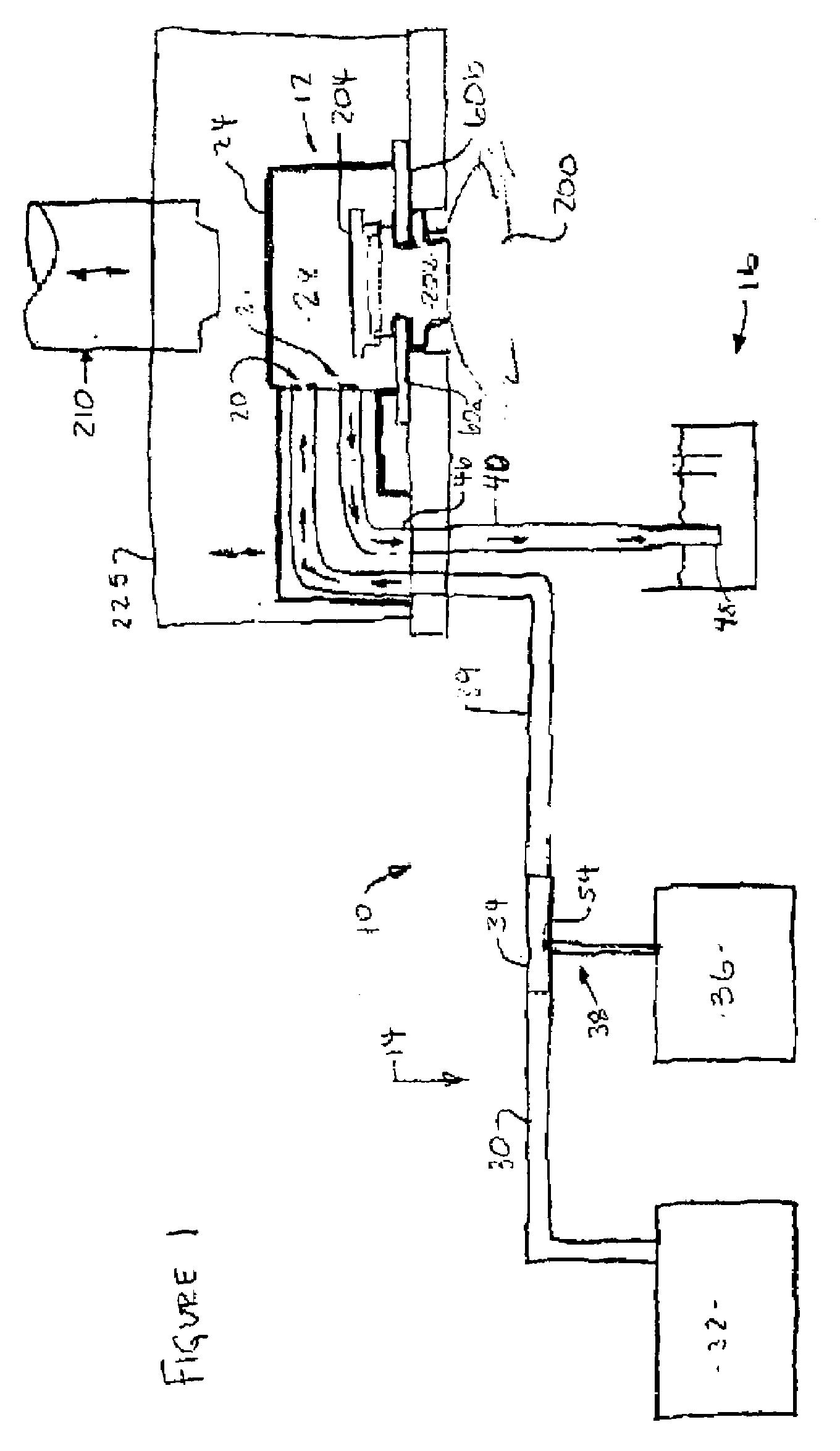
[0038]Referring now to the drawings and in particular to FIG. 1, sterilization system is shown generally at 10. System 10 is suitable for use in association with filler devices. The filler devices are generally suitable for the filling of flexible b...


PUM

PropertyMeasurementUnit
temperatureaaaaaaaaaa
pressureaaaaaaaaaa

Abstract

A sterilization system for use in association with a filler device configured for filling at least one of rigid and flexible containers comprising a sterilization chamber and a sterilant supply assembly. The sterilization chamber includes a housing, an inlet into the housing, an outlet from the housing and a product retainer assembly. These components define a cavity within which to position a portion of a fitment. The sterilant supply assembly comprises a steam generating system having a steam supply conduit extending therefrom and a joint mixing conduit coupled with the inlet into the housing of the sterilization chamber, a hydrogen peroxide storing system and a member for metering liquid phase hydrogen peroxide from the hydrogen peroxide storing system into the steam supply conduit for mixing therewith, and, in turn, introduction thereof into the cavity of the sterilization chamber.

Description

BACKGROUND OF THE INVENTION[0001]1. Field of the Invention[0002]The invention relates in general to sterilization systems, and more particularly, to a sterilization system which is suitable for the sterilization of rigid containers and flexible bags and which uses steam combined with hydrogen peroxide injection.[0003]2. Background Art[0004]Sterilization chambers and sterilization processes are well known in the art. Such processes associated with container filling are shown in U.S. Pat. No. 4,458,734 issued to Scholle et al and in U.S. Pat. No. 4,498,508 issued to Scholle et al. The entire specification of these two patents is hereby incorporated by reference. These references disclose the use of dry heat to sterilize various components during the filling process.[0005]The use of steam as a sterilant for sterilizing portions of containers prior to filling is well known in the art. Similarly, the utilization of hydrogen peroxide as a sterilant for sterilizing portions of containers p...

Claims


Application Information

Patent Timeline
Patent Type & Authority Applications(United States)
IPC IPC(8): A61L2/20
CPCA61L2/07A61L2/208B65B55/10B65B55/022A61L2202/122
Inventor SAVAGE, CHESTERSTRICKLIN, DOUGLAS K.
Owner SCHOLLE CORP
Why Eureka
Try Eureka