Inkjet recording apparatus

a recording apparatus and inkjet technology, applied in the direction of electrographic process apparatus, instruments, printing, etc., can solve the problems of inability to remove foreign matter from the surface of the recording medium with the remover, defect or failure of ejection of ink droplets, and the external force or vibration of the recording medium, so as to achieve the effect of reducing the scattering of foreign matter

Active Publication Date: 2008-01-31
BROTHER KOGYO KK
View PDF24 Cites 8 Cited by
  • Summary
  • Abstract
  • Description
  • Claims
  • Application Information

AI Technical Summary

Benefits of technology

[0007]This invention has been developed in light of the above-described situations, and it is an object of the invention, therefore, to provide an inkj

Problems solved by technology

Further, a recording medium is subject to an external force or vibrations while fed inside the printer.
Some of the foreign matter thus scattering may waft around the feeder belt and land on the ink ejection surface of the inkjet head, leading to closure of the nozzle openings or entrance of the foreign matter into the nozzles, which caus

Method used


Image

  • Inkjet recording apparatus
  • Inkjet recording apparatus
  • Inkjet recording apparatus

Examples


first embodiment

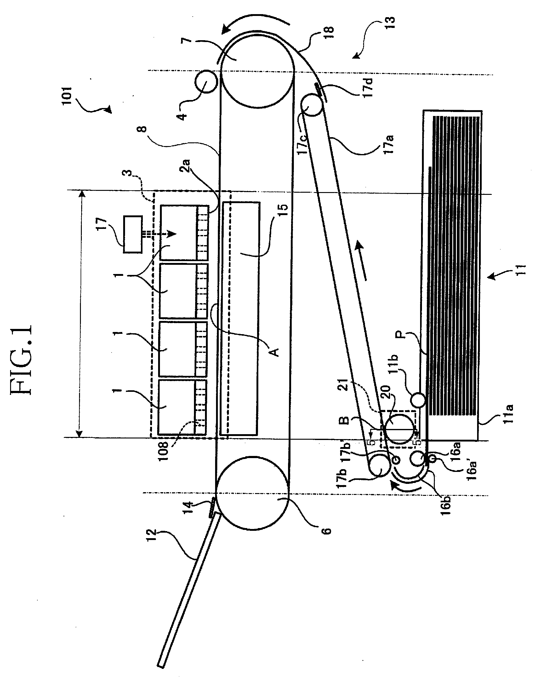
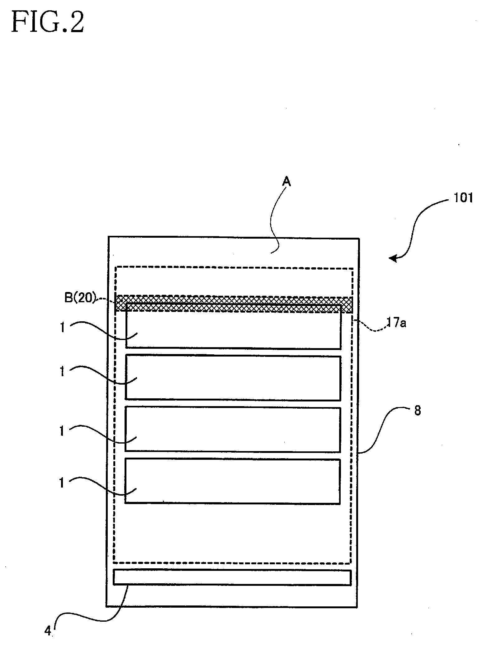
[0031]Referring to FIGS. 1 to 5, there will be described an inkjet recording apparatus according to the invention which takes the form of an inkjet printer.

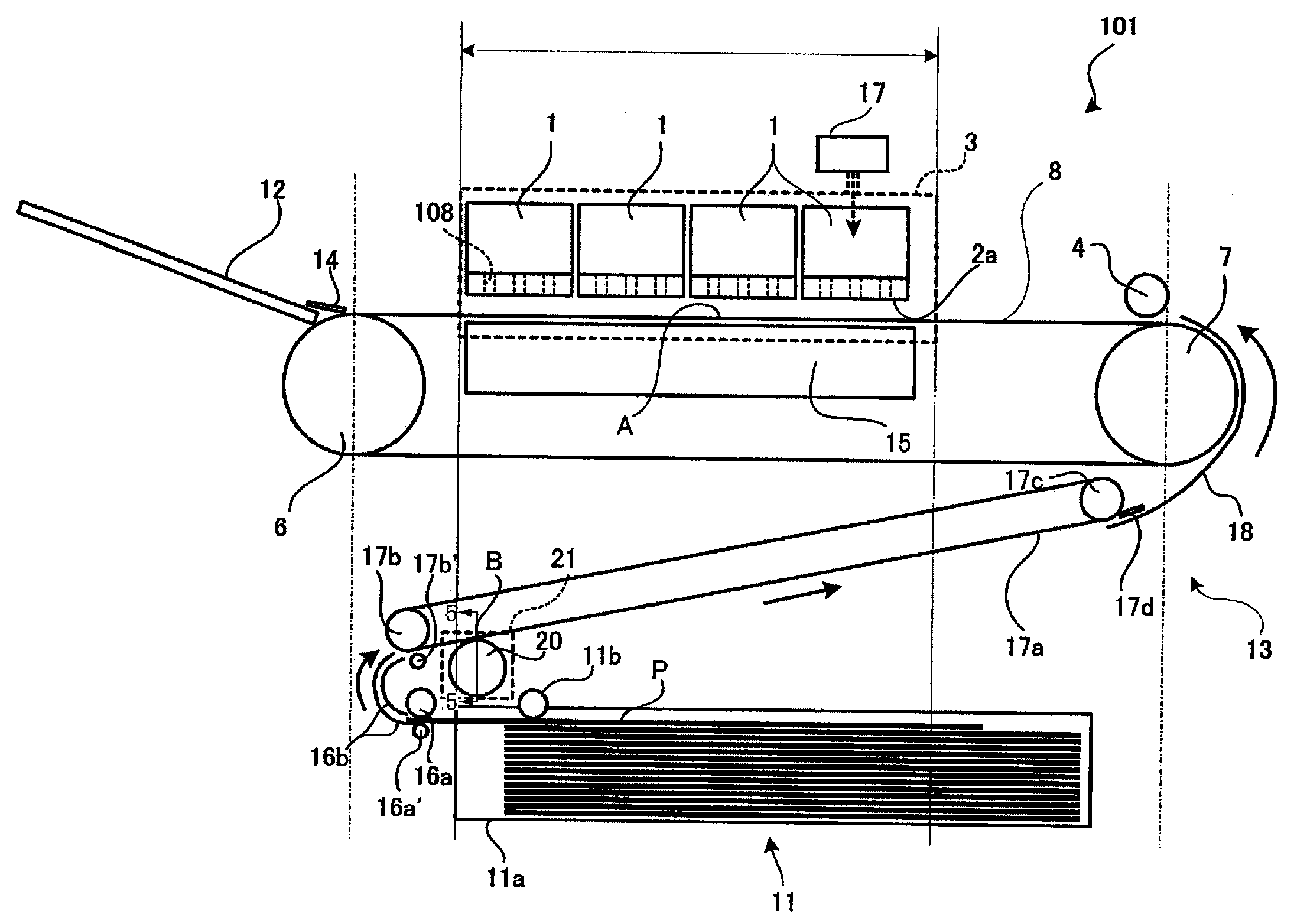
[0032]In FIG. 1, reference numeral 101 generally denotes the inkjet printer according to the first embodiment. The inkjet printer 101 has four inkjet heads 1, that is, the inkjet printer is a color printer. Inside the inkjet printer 101 are disposed a sheet supply device 11 as a medium supply device, a remover roller 20 as a remover, a feeding device 13, and a catch tray 12, which 11, 20, 13, 12 are arranged in the order of description along a feed path of a recording medium P, e.g., a cut sheet of paper. The feed path is indicated by solid arrows in FIG. 1.

[0033]The sheet supply device 11 includes a sheet holder 11a as a medium holder, a pickup roller 11b, guide rollers 16a, 16a′, and a pair of guide plates 16b, namely, an inner guide plate and an outer guide plate. The guide plates 16b function as a first turnover guide. The sh...

second embodiment

[0048]Although in the above-described embodiment, the feed path in the inkjet printer 101 along which the cut sheet P is fed is S-shaped in side view, the feed path may have other shapes. For instance, the feed path may be U-shaped. Hereinafter, there will be described an inkjet printer 201 according to the invention, in which the feed path is U-shaped, by referring to FIG. 6.

[0049]In the second embodiment, the intermediate feeder belt 17a used in the first embodiment is omitted, and a cut sheet P as turned over or turned 180-degree by a turnover guide plate 216b is made to pressure-sensitively adhere to a downward-facing surface 208a of a feeder belt 208.

[0050]In the first embodiment, the cut sheet P is guided and turned over by a pair of guide plates 16b, namely, an outer guide plate and an inner guide plate. In the second embodiment, on the other hand, the inner guide plate 16b is omitted and a guide roller 216a having a relatively large diameter is employed, and the cut sheet P ...


PUM


Abstract

There is disclosed an inkjet recording apparatus including a feeding device, a remover, and an inkjet head. The feeding device feeds a recording medium along a feed path passing through a removing area. A part of an opposingly-feeding surface extends opposed to the ink jet head and along the feed path, and the removing area is located under the opposingly-feeding surface and within the opposingly-feeding surface as seen in a vertical direction. The remover removes foreign matter from a surface of the recording medium during the recording medium is fed through the removing area by the feeding device. The inkjet head is disposed downstream of the remover with respect to a feeding direction in which the recording medium is fed. The inkjet head has an ink ejection surface in which a nozzle is open, and an ink droplet is ejected from the nozzle toward a recording surface of the recording medium while the recording medium is fed along at least a part of the opposingly-feeding surface.

Description

CROSS REFERENCE TO RELATED APPLICATION[0001]The present application claims priority from Japanese Patent Application Nos. 2006-208692 and 2006-207833, both of which were filed on Jul. 31, 2006, the disclosure of which is herein incorporated by reference in its entirety.BACKGROUND OF THE INVENTION[0002]1. Field of the Invention[0003]The present invention relates to an inkjet recording apparatus for forming or recording an image on a recording medium.[0004]2. Description of Related Art[0005]An inkjet printer as a type of the inkjet recording apparatus is disclosed in JP-A-2006-131353. The inkjet printer includes an inkjet head, a feeder belt, and a medium holder. The inkjet head has an ink ejection surface in which openings of a plurality of nozzles are arranged, and the medium holder is capable of accommodating a stack of recording media, which may be cut sheets of paper. Recording media stacked on the medium holder are one by one picked up from the medium holder and fed by the feede...

Claims


Application Information

Patent Timeline
IPC IPC(8): B41J2/01
CPCB41J11/0015B41J29/17B41J11/007
Inventor NAKAYAMA, KOJI
Owner BROTHER KOGYO KK
Why Eureka
Try Eureka