
Heat exchanger

a heat exchanger and heat exchanger technology, applied in the direction of semiconductor/solid-state device details, lighting and heating apparatus, etc., can solve the problems of not always achieving anticipated corrosion inhibition effect, unplanned potential gradient, etc., to improve the corrosion resistance of each brazing sheet, improve the corrosion resistance and raise the cooling efficiency of the heat exchanger 100

Inactive Publication Date: 2014-06-12
TOYOTA JIDOSHA KK
View PDF6 Cites 8 Cited by
  • Summary
  • Abstract
  • Description
  • Claims
  • Application Information

AI Technical Summary

Benefits of technology

This invention is a heat exchanger that uses a special layer to prevent corrosion and pitting in its clad materials. The heat exchanger has layers of material that contain brazing filler metal or sacrificial material, which diffuse during brazing to form a potential gradient layer that protects against corrosion. The thick and thin clad sheets have high zinc content, which further enhances the layer's effectiveness. This results in a more robust heat exchanger that can withstand high cooling water flow rates and prevent pitting and erosion in its clad materials. The potential gradient layer also improves the cooling performance and allows for a thinner design of the heat exchanger.

Problems solved by technology

However, the following problem can occur when the attempt has been made to use a potential gradient layer to impart corrosion resistance to a top sheet 102 made of a clad thin sheet material in a heat exchanger 100 with the structure described above: even when a heat exchanger 100 has been designed with the goal of forming a corrosion-inhibiting potential gradient layer at the top sheet 102 made of a clad thin sheet material, the intended potential gradient has not always been formed by the clad material after brazing and the anticipated corrosion-inhibiting effect has thus not always been obtained.

Method used


Image

  • Heat exchanger
  • Heat exchanger
  • Heat exchanger

Examples


first embodiment

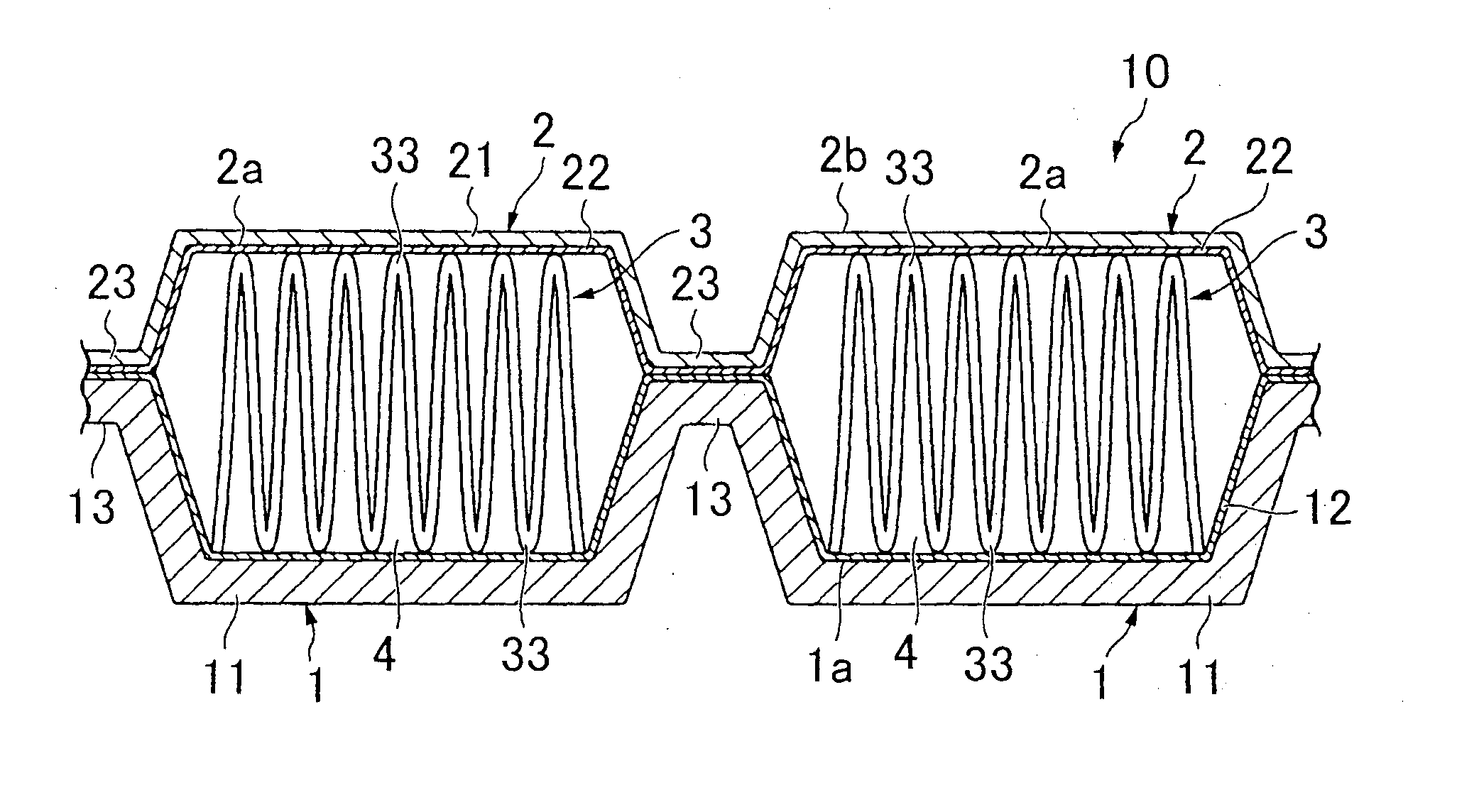
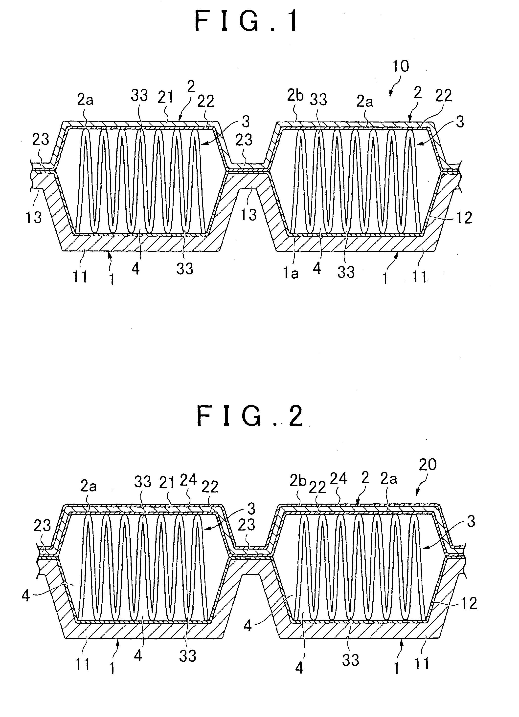
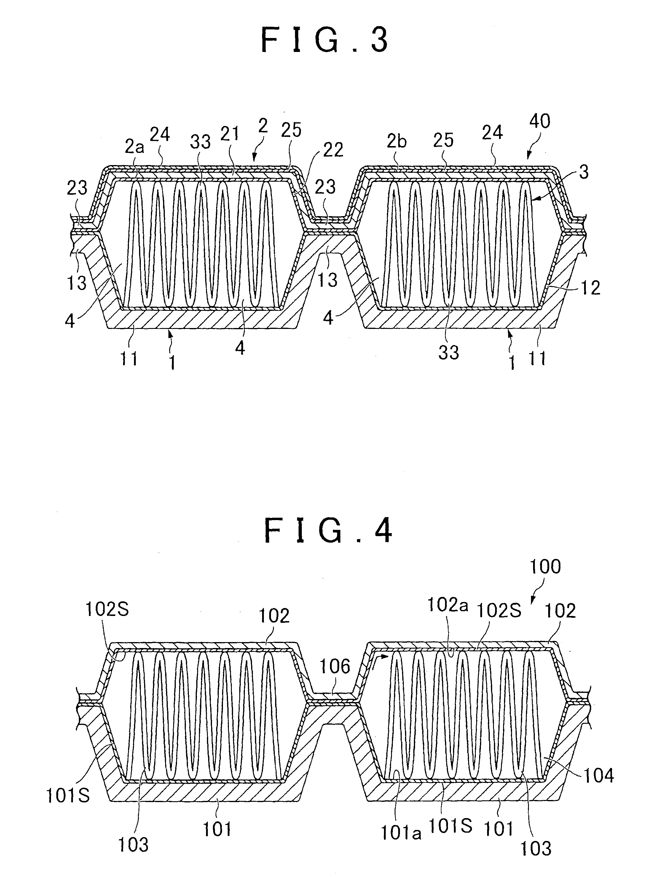
[0026]A first embodiment of the heat exchanger according to the invention will be first described. FIG. 1 is a schematic cross-sectional diagram that shows the first embodiment of a heat exchanger according to the invention. The heat exchanger 10 shown in FIG. 1 is constructed by stacking a clad thick sheet material 1, which forms the bottom sheet, an inner fin 3, and a clad thin sheet material 2, which forms the top sheet, in the given sequence and, using the individual brazing filler metal layers 12, 22 disposed on the interior surfaces of the individual clad materials 1, 2, brazing the clad materials 1, 2 together at the joint regions 13, 23 and brazing the inner fin 3 to the surfaces 1a, 2a.

[0027]The clad thick sheet material (bottom sheet) 1 and the clad thin sheet material (top sheet) 2 define a passage 4 through which cooling water (coolant) flows. The clad thick sheet material 1 has a sheet shape, and a step portion (joint region) 13, which bonds with the joint region 23 of...

second embodiment

[0051]A second embodiment of the heat exchanger according to the invention will next be described. Those structures in the second embodiment that are similar to those of the previously described first embodiment will not be described in detail again. The heat exchanger of this second embodiment is configured in a manner similar to that in which the first embodiment is configured, except that, in the heat exchanger 10 in the preceding embodiment, the clad thin sheet material 2 has a sacrificial material layer in place of the brazing filler metal layer 22 and the inner fin 3 is a clad material that has a core material and a brazing filler metal layer that covers only the clad thin sheet material side of the core material or both sides of the core material.

[0052]The sacrificial material layer is disposed so as to cover the surface of the passage 4 side of the core material 21. This sacrificial material layer is formed of an aluminum alloy that contains Zn and at least one selected from...

third embodiment

[0057]A heat exchanger according to a third embodiment will next be described. No description will be provided for those structures in the third embodiment that are similar to those of the previously described first embodiment. FIG. 2 is a schematic cross-sectional diagram that shows a heat exchanger according to a third embodiment. The heat exchanger 20 in this third embodiment is configured in a manner similar to that in which the previously described first embodiment is configured, except that the clad thin sheet material 2 has a three layer structure that has a brazing filler metal layer 24 on the side opposite from the passage 4.

[0058]The brazing filler metal layer 24 is disposed so as to cover the surface 2b of the core material 21 on the side opposite from the passage 4 side. This brazing filler metal layer 24 is formed of an aluminum alloy brazing filler metal that contains 5.0 to 12.6 mass % of Si with the balance being Al and unavoidable impurities.

[0059]Effects similar to...


PUM

PropertyMeasurementUnit
thicknessaaaaaaaaaa
thicknessaaaaaaaaaa
temperatureaaaaaaaaaa

Abstract

A heat exchanger has a clad thin sheet material, a clad thick sheet material that is disposed so as to define a passage between the clad thick sheet material and the clad thin sheet material, and that has a sheet thickness greater than that of the clad thin sheet material, and an inner fin held between the clad materials. The clad thick sheet material and the clad thin sheet material have Zn-containing brazing filler metal layers on their passage sides, respectively, and the post-brazing surface Zn amounts are set so as to satisfy specific conditions. Further, certain conditions concerning the compositions of each of the layers that constitute the clad materials, and the inner fin are set.

Description

BACKGROUND OF THE INVENTION[0001]1. Field of the Invention[0002]The invention relates to a heat exchanger that is mounted in an electric automobile or a hybrid automobile, or on any of various electronic device circuits, and that cools a heat-generating device such as a semiconductor device.[0003]2. Description of Related Art[0004]Heat exchangers that cool heat-generating devices such as semiconductor devices are mounted in electric automobiles or hybrid automobiles, or on various electronic device circuits. One example of a conventional heat exchanger of this type is shown in FIG. 4. This heat exchanger 100 is of a water-cooled type, in which cooling water is used as the coolant, and has: a top sheet 102, which is formed of an aluminum alloy sheet, to which to attach a cooling target such as a semiconductor device; a bottom sheet 101 of an aluminum alloy sheet, which defines a passage 104 between the bottom sheet 101 and the top sheet 102; and an inner fin 103, which is held betwee...

Claims


Application Information

Patent Timeline
Patent Type & Authority Applications(United States)
IPC IPC(8): F28F21/08
CPCB23K35/0238B23K35/286B32B15/016C22C21/00C22C21/02C22C21/10C22C21/14F28F3/025F28F3/12F28F21/084F28F21/089F28F2275/04H01L21/4882H01L23/3736H01L23/473H01L2924/0002H01L2924/00
Inventor KURODA, SHUYOSHINO, MICHIHIDEOHNO, KAZUTAKAFUKAMI, TOMOSUGINO, YUJI
Owner TOYOTA JIDOSHA KK
Learn More