
Deblocking filter

a filter and block-wise technology, applied in the field of decoding of block-wise coded video pictures, can solve the problems of large bit volumes, inability to transfer over conventional communication networks and transmission lines in real time, and the inability to enable real-time video transmission requires a large extent of data compression, so as to reduce the effect of blocking artifacts

Active Publication Date: 2008-01-31
CISCO TECH INC
View PDF5 Cites 58 Cited by
  • Summary
  • Abstract
  • Description
  • Claims
  • Application Information

AI Technical Summary

Benefits of technology

[0016] The present invention discloses a method in video decoding for reducing blocking artifacts between a first and a second block in a block wise coded video picture by performing a test on pixel lines crossing a boundary and / or an extension of the boundary between the first and the second block and executing a de-blocking filter operation on boundary neighboring pixels if the test indicates artifacts, wherein the method further includes performing the test on a subset of the pixel lines only, and if the test indicates artifacts, executing a de-blocking filter operation on the boundary neighboring pixels in each of the pixel lines crossing the boundary.

Problems solved by technology

However, representing moving pictures requires bulk information as digital video typically is described by representing each pixel in a picture with 8 bits (1 Byte) Such uncompressed video data results in large bit volumes, and can not be transferred over conventional communication networks and transmission lines in real time due to limited bandwidth.
Thus, enabling real time video transmission requires a large extent of data compression.
Data compression may, however, compromise with picture quality.
Direct representation of the transform coefficients is still too costly for many applications.
However, one of the drawbacks is that the reconstructed image may visible artifacts corresponding to the blocks used for prediction and residual signal coding.
However, the integrated solution is a quite processor consuming i.a. as it requires a test procedure for each pixel line crossing the block edges to be smoothed.

Method used


Image

  • Deblocking filter
  • Deblocking filter
  • Deblocking filter

Examples


first embodiment

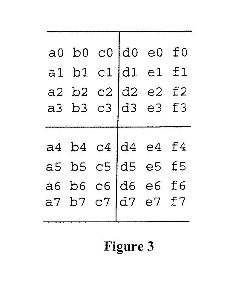
[0051] As the present invention, the second line in the FIG. 4 is selected as the “decision line” for the four lines 0-3 crossing the boundary.

[0052] Then, filtering of all 4 edge lines are performed if:

d=(|a1−2b1+c1|+|d1−2e1+f1|)QP)

[0053] Otherwise no filtering is performed.

[0054] As opposed to prior art, the test for one line applies for all the lines crossing the block boundary. Thus, the value β is not necessarily determined in the same way as the β earlier described herein. E.g. other look-up tables than those depicted in FIGS. 4 and 5 may be used to determine β.

second embodiment

[0055] In the present invention, the third and the sixth line of in FIG. 4 in combination are used as the “decision lines” for all the eight lines 0-7 crossing the boundary.

[0056] Then, filtering of all 8 edge lines are performed if:

d′=(|a2−2b2+c2|+|d2−2e2+f2|+|a5−2b5+c5|+|d5−2e5+f5|)QP)

[0057] Otherwise no filtering is performed. β′ may also be determined in still a another way than in prior art. A typical relation to β of the first embodiment would be β′=2β.

[0058] Further, if the above tests on the “decision line” is true, a separate calculation is performed for each of the line for deriving delta and a corresponding corrected pixel values. This can generally be expressed as in the following, using the same notation as for the description of prior art:

Δ=(a−b−2c+2d+e−f) / 4

[0059] Alternatively, for accommodating the calculation to the state of the art processor commonly used in codecs for videoconferencing, expression above could be transformed to: Δ=d+a+e22-c+b+f22

[0060] The delta ...


PUM


Abstract

The invention is related to decoding of block wise coded video pictures. The determination of using de-blocking filtering between coded blocks is based on alternative characteristics compared to the characteristics used in H.264 / AVC.

Description

CROSS REFERENCE TO RELATED APPLICATIONS [0001] This application is a continuation of U.S. application Ser. No. 11 / 250,187 filed on Oct. 13, 2005, all of which claim priority to Norwegian Patent Application No. 20051721 filed on Apr. 7, 2005 and Norwegian Patent Application No. 20044349 filed on Oct. 13, 2004. The contents of each of these documents are incorporated herein by reference.FIELD OF THE INVENTION [0002] The invention is related to decoding of block wise coded video pictures. BACKGROUND OF THE INVENTION [0003] Transmission of moving pictures in real-time is employed in several applications like e.g. video conferencing, net meetings, TV broadcasting and video telephony. [0004] However, representing moving pictures requires bulk information as digital video typically is described by representing each pixel in a picture with 8 bits (1 Byte) Such uncompressed video data results in large bit volumes, and can not be transferred over conventional communication networks and transm...

Claims


Application Information

Patent Timeline
IPC IPC(8): G06K9/40H03MH04N7/26H04N7/50
CPCH04N19/139H04N19/159H04N19/176H04N19/86H04N19/117H04N19/14H04N19/82H04N19/61
Inventor BJONTEGAARD, GISLE
Owner CISCO TECH INC
Learn More