
Combined Cable Guiding/Clamping Device

a technology of guiding/clamping device and cable, which is applied in the direction of coupling device connection, electrically conductive connection, electrical apparatus, etc., can solve the problems of obvious increase in labour cost, and achieve the effects of easy and cheaper production, easy and fast operation, and limited thickness

Inactive Publication Date: 2008-01-31
NECTO GROUP
View PDF4 Cites 2 Cited by
  • Summary
  • Abstract
  • Description
  • Claims
  • Application Information

AI Technical Summary

Benefits of technology

"The technical problem addressed in this patent is the need for a cable guiding / clamping device that is easy, flexible, and repeatable for assembly of electric cables in electric apparatus such as household appliances. The device should allow for quicker and cheaper production, stable fixing of the cable, and a reduction in the amount of material required for manufacture. Additionally, the device should allow for pre-wiring and testing of components outside of the electric household appliance. The present invention provides a combined cable guide / clamp that meets these requirements."

Problems solved by technology

It is known, in the technical sector relating to electric cables, that difficulties exist as regards the need to provide preassembled wiring cables such that they have a plug or the like at one end and the terminal block to be connected to the electric household appliance or electrical apparatus at the other end.
It is known that the greatest difficulties in designing these preassembled cables arise from the need to have, at the end for connection to the electric household appliance, a part which is able to guide the cable from the outside to the inside of the closing wall of the appliance and firmly retain the cable in order to avoid separation resulting from accidental pulling forces, providing on the inside an end which can be connected, by means of a terminal block, connector or the like, to the internal wiring of the electric household appliance.
Although fulfilling their function, these cable grips however have some practical drawbacks arising from the presence of the screws which, apart from forming an additional component of the assembly, with its own cost, must be subsequently fitted during production with an obvious increase in the labour costs.
Although fulfilling its function, this cable guide has drawbacks arising from the fact that the seat for the cable consists of a hole perpendicular to the direction of extension of the cable, which does not facilitate bending of the cable so that it is able to pass through from the outside to the inside in particular in the case of large diameters.

Method used


Image

  • Combined Cable Guiding/Clamping Device
  • Combined Cable Guiding/Clamping Device
  • Combined Cable Guiding/Clamping Device

Examples


Embodiment Construction

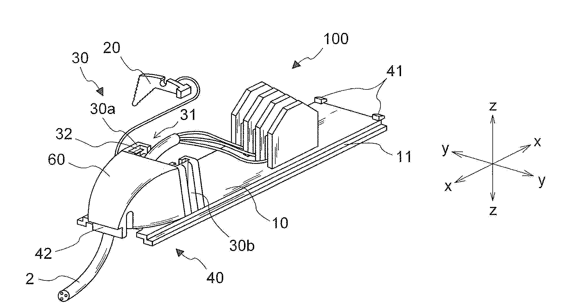
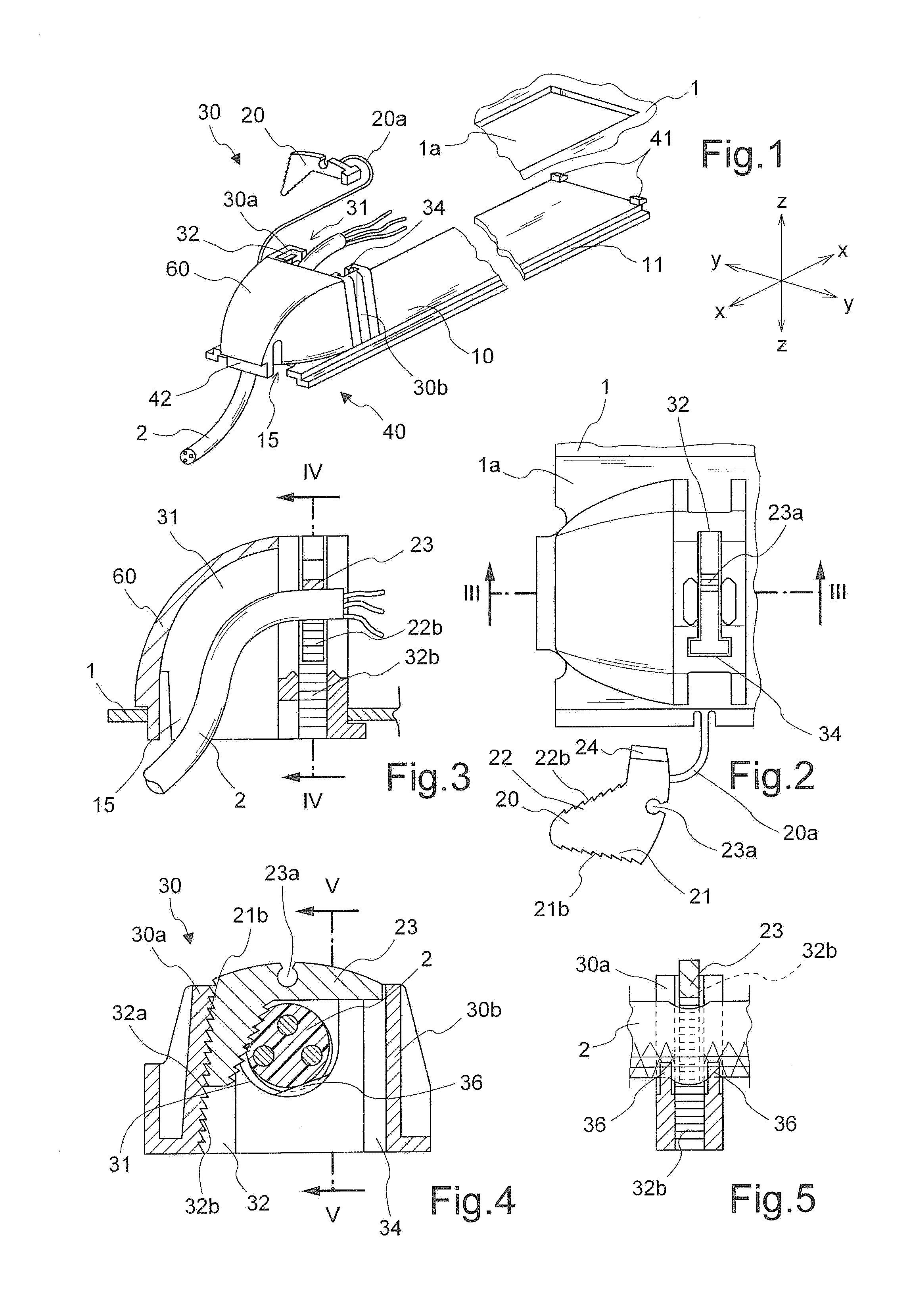
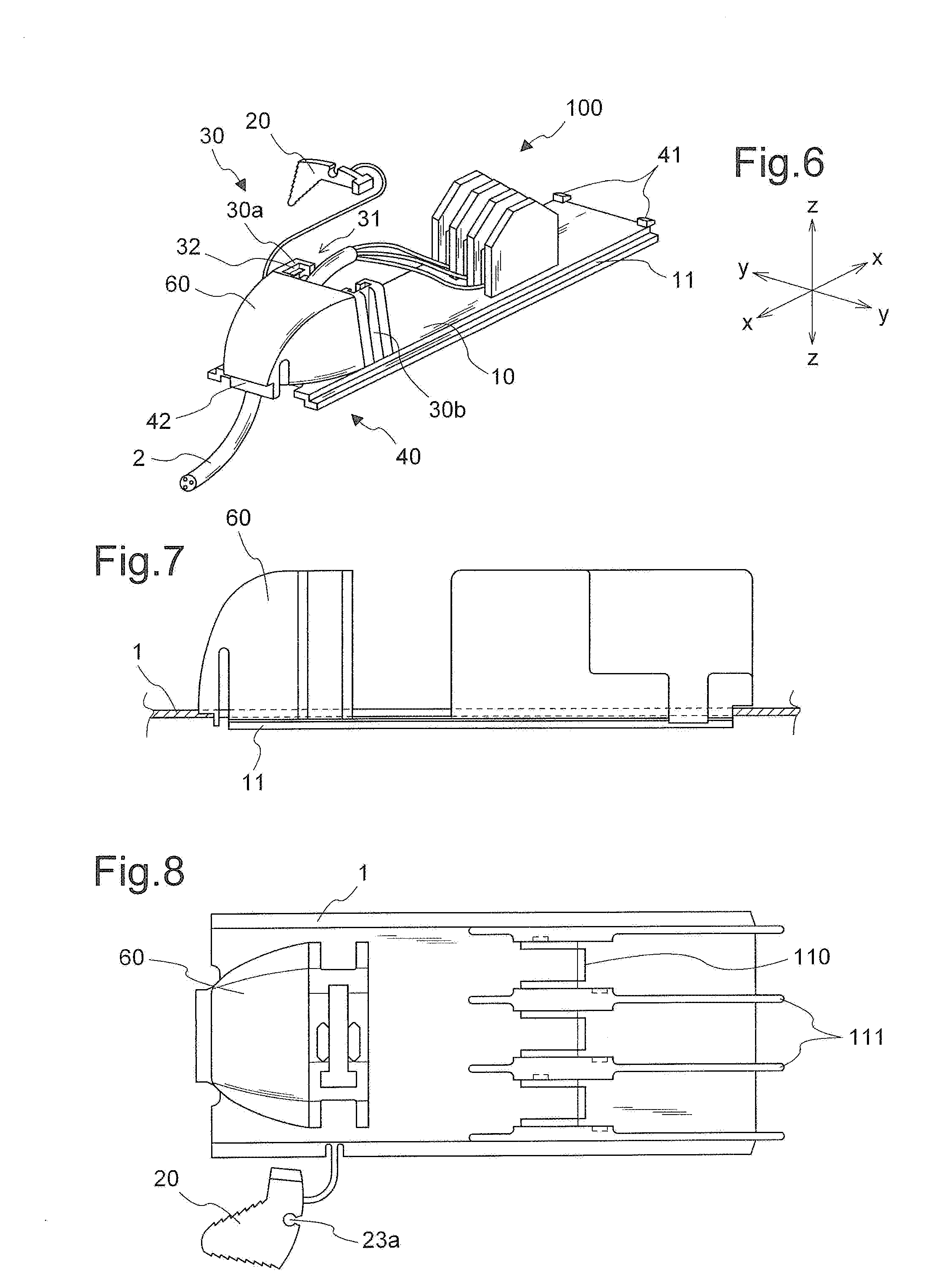
[0022]As shown in FIG. 1 and with reference to a set of three reference axes assumed solely for the sake of convenience of the description, i.e. longitudinal axis X-X, transverse axis Y-Y and vertical axis Z-Z, in relation to the orientation layout in the figures, the cable guiding / clamping device according to the present invention comprises essentially a base-piece 10 extending in a longitudinal direction X-X over a length slightly smaller than the corresponding dimension of the opening 1a in an electric household appliance, schematically indicated with its wall 1; said base-piece has longitudinal sides which are formed with transverse undercuts or guides 11 extending longitudinally and able to form a front contact edge for applying the cable guide / clamp to said wall 1.

[0023]At one of the two opposite longitudinal ends, the cable guide / clamp has two teeth 41 projecting outwards and able to form the part of the engagement elements 40 which also comprise a lug 42 resiliently deformab...


PUM


Abstract

Combined cable guiding and clamping device comprising a support base-piece provided with guides and engagement elements for engagement with the wall of an electric apparatus (such as an appliance) and an opening suitable for the insertion of a cable, said base-piece incorporating a cable clamping device and a body for protecting the cable.

Description

BACKGROUND[0001]1. Technical Field of the Invention[0002]The present invention relates to a combined cable guiding / clamping device.[0003]2. Description of the Prior Art[0004]It is known, in the technical sector relating to electric cables, that difficulties exist as regards the need to provide preassembled wiring cables such that they have a plug or the like at one end and the terminal block to be connected to the electric household appliance or electrical apparatus at the other end.[0005]It is known that the greatest difficulties in designing these preassembled cables arise from the need to have, at the end for connection to the electric household appliance, a part which is able to guide the cable from the outside to the inside of the closing wall of the appliance and firmly retain the cable in order to avoid separation resulting from accidental pulling forces, providing on the inside an end which can be connected, by means of a terminal block, connector or the like, to the interna...

Claims


Application Information

Patent Timeline
Patent Type & Authority Applications(United States)
IPC IPC(8): H01R13/11
CPCH01R13/745H01R13/5812
Inventor PIZZI, GIORDANO
Owner NECTO GROUP
Learn More