Apparatus and methods for uterine anesthesia

a technology of uterine anesthesia and apparatus, applied in the field of apparatus and methods for providing uterine anesthesia, can solve the problems of reducing the amount of anesthetic available for numbing the uterine region, no means for injecting anesthetic, and not preventing the drainage of anesthetic out the uterus

Inactive Publication Date: 2008-01-31
FEMSUITE
View PDF11 Cites 2 Cited by
  • Summary
  • Abstract
  • Description
  • Claims
  • Application Information

AI Technical Summary

Benefits of technology

The objective of this patent is to create devices and techniques for giving anesthetics to the uterus while minimizing the amount of medication lost during the process.

Problems solved by technology

This patent describes how to improve the delivery of anesthetic to the uterine region when performing gyneological procedures. A technical problem addressed is the issue of anesthetic draining out of the uterus through the opening created by the placement of a tubular instrument called a pipelle. Other solutions involve inserting a balloon or other mechanical barrier to block the passage of anesthetic from the uterus back up the cervical tract, but these measures come with their own set of challenges and risks. Therefore, there is a desire for new devices and techniques that effectively deliver anesthetic without causing excessive damage or discomfort to patients.

Method used


Image

  • Apparatus and methods for uterine anesthesia
  • Apparatus and methods for uterine anesthesia

Examples


Embodiment Construction

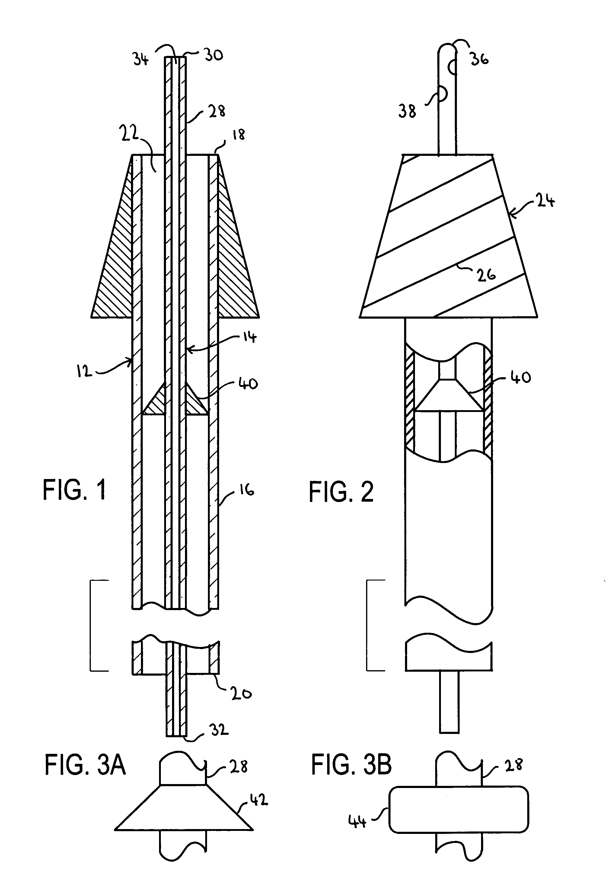
[0029]The present invention is related to apparatus and methods for delivering an anesthetic medication to the uterine region and for preventing the undesired drainage of the anesthetic out of the uterine region. In a preferred embodiment, the anesthetic is injected through a pipelle that translates within the lumen of an outer tube and that is surrounded by a stopper creating a seal with the lumen of the outer tube. The anesthetic is then prevented from draining through the interstice between the pipelle and the lumen. An applicator maintains the outer tube anchored within the cervical os and prevents a loss of the anesthetic along the cervical walls.

[0030]Referring to FIG. 1, an exemplary embodiment of an apparatus for uterine anesthesia constructed in accordance with the principles of the present invention is described. Apparatus for uterine anesthesia 10 includes two basic components, outer member 12 and inner member 14. In turn, outer member 12 includes outer tube 16 having dis...


PUM


Abstract

The present invention is related to an apparatus for uterine anesthesia that comprises an outer tube and an inner tube positioned within the outer tube. The apparatus is positioned in the cervical os of a patient and an anesthetic is dispensed through the inner tube. A stopper surrounding the inner tube prevents a drainage of the anesthetic through the interstice between the two tubes, while an applicator surrounding the outer tube prevents a loss of the anesthetic along the cervical walls and into the vaginal canal. The applicator also maintains the cervical os in a dilated position, operating as a tenaculum and providing access to the uterus by a clinician. Methods for providing uterine anesthesia are also provided.

Description


Claims


Application Information

Patent Timeline
Owner FEMSUITE
Why Eureka
Try Eureka