
Rear view system and adjusting method thereof

a rear view system and rear view technology, applied in the field of rear view systems, can solve the problems of accidents still occurring at crossroads and other places where vehicles are parked

Inactive Publication Date: 2008-02-14
CHEN FU JENG
View PDF1 Cites 4 Cited by
  • Summary
  • Abstract
  • Description
  • Claims
  • Application Information

AI Technical Summary

Benefits of technology

[0007]It is therefore an aspect of the present invention to provide a rear view system for a transportation device which can automatically adjust the visual angle of a rear view means according to the movement of the transportation device.
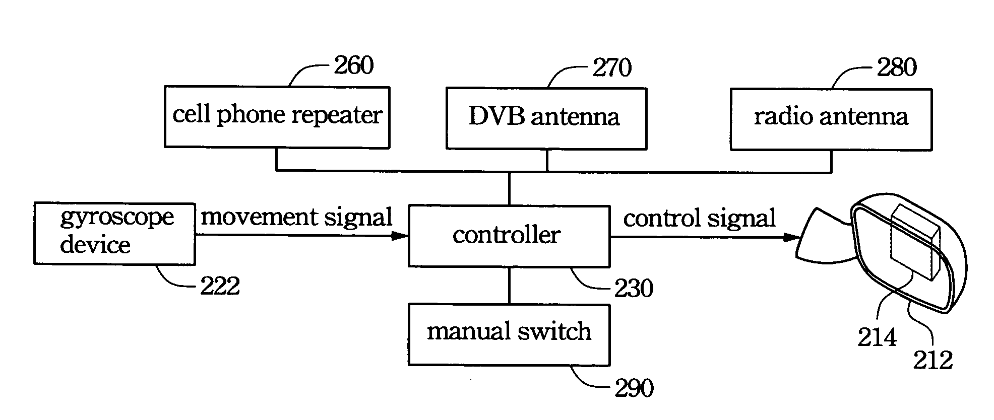
[0008]In accordance with the foregoing and other aspects of the present invention, a rear view system for a transportation device including a rear view means, a sensor and a controller is provided. The sensor is used to generate a movement signal according to the movement of the transportation device. The controller is used to control the rotation of the rear view means according to the movement signal. The transportation device may be a vehicle, a motorcycle or a ship. Furthermore, the rear view means may be a rear view mirror. The following embodiment will assume the transportation device is a vehicle for easy to illustrate.
[0015]It is another aspect of the present invention to provide a method for adjusting the visual angle of a rear view means equipped in a transportation device. The method rotates the rear view means according to the movement of the transportation device, so that a driver of the transportation device can obtain a better field of rear vision to avoid accidents.
[0018]In conclusion, the rear view system according to the present invention can automatically adjust the visual angle of the rear view means according to the movement of the transportation device. Thus, the driver can obtain a better field of rear vision, so that the driver can drive more safely.

Problems solved by technology

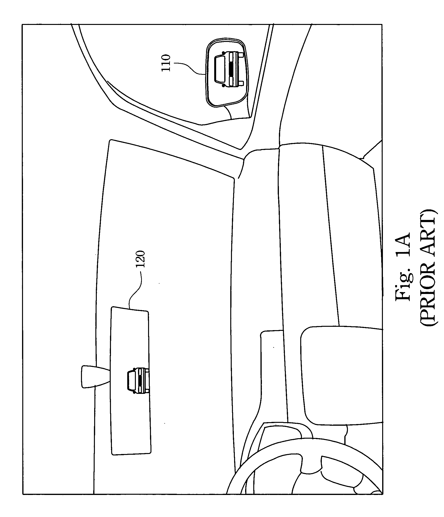
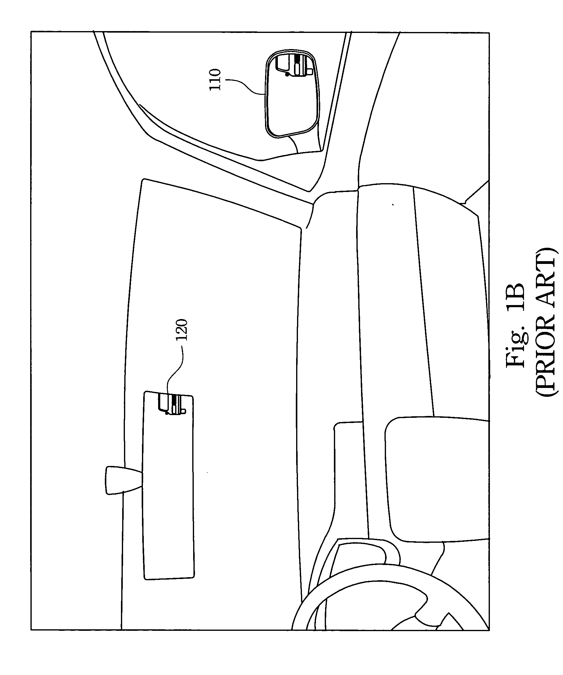
Thus, although the driver takes great care when turning right or turning left, accidents still occur at crossroads and other places where vehicles may turn.

Method used


Image

  • Rear view system and adjusting method thereof
  • Rear view system and adjusting method thereof
  • Rear view system and adjusting method thereof

Examples


Embodiment Construction

[0028]Reference will now be made in detail to the present preferred embodiments of the invention, examples of which are illustrated in the accompanying drawings. Wherever possible, the same reference numbers are used in the drawings and the description to refer to the same or like parts.

[0029]Reference is made to FIG. 2A which is a block diagram of a rear view system according to one preferred embodiment of this invention. In FIG. 2A, the rear view system for a transportation device includes a rear view means 210, a sensor 220 and a controller 230. The sensor 220 is used to generate a movement signal according to the movement of the transportation device. The controller 230 is used to control the rotation of the rear view means 210 according to the movement signal. The transportation device may be a vehicle, a motorcycle or a ship. Furthermore, the rear view means 210 may be a rear view mirror. The following embodiment will assume the transportation device is a vehicle for easy to i...


PUM


Abstract

A rear view system for a transportation device includes a rear view means, a sensor and a controller. The sensor is used for generating a movement signal according to the movement of the transportation device. The controller is used for controlling the rotation of the rear view means according to the movement signal. Moreover, a method for adjusting the visual angle of a rear view means equipped in a transportation device is also disclosed.

Description

BACKGROUND[0001]1. Field of Invention[0002]The present invention relates to a rear view system. More particularly, the present invention relates to a rear view system that can automatically adjust the field of rear vision for a driver of a transportation device.[0003]2. Description of Related Art[0004]In the past century, the transportation industry has made great progress, especially in the automobile industry. As production techniques and materials improve, vehicles are becoming much better. The prosperity of the vehicle industry also induces advances in related fields. However, high-end sedans and sports utility vehicles or ordinary cars always emphasize on the same two issues, i.e., safety and comfort. Therefore, vehicle industry does not only rely on its own techniques for vehicle development, but also on progress in related fields.[0005]Vehicle safety is the most important consideration for vehicle designers, vehicle manufacturers, and drivers. In a moving vehicle, the driver ...

Claims


Application Information

Patent Timeline
Patent Type & Authority Applications(United States)
IPC IPC(8): G02B5/08
CPCB60R1/04B60R1/07B60R2001/1261B60R2001/1223B60R1/12
Inventor CHEN, FU-JENG
Owner CHEN FU JENG
Learn More