Electronic candle

a technology of electric candles and candles, which is applied in the field of electric illumination devices, can solve the problems of property, affecting the safety of candles, and affecting the safety of people, and all such prior attempts have been found to be less than satisfactory

Inactive Publication Date: 2008-02-14
JARAMILLO JAMISON
View PDF13 Cites 61 Cited by
  • Summary
  • Abstract
  • Description
  • Claims
  • Application Information

AI Technical Summary

Benefits of technology

[0007]Disclosed herein is an electronic illumination device which simulates the operation of a candle. The illumination device includes a light source which is operable to deliver illumination having at least two different spectral patterns. The light source can further operate to deliver spatial and temporal patterns of illumination and in this manner can provide for a three-dimensional simulated flame. The light source, in some embodiments, includes light emitting diodes, which may be RGB diodes of the type which include a red emitter, a green emitter and a blue emitter. These emitters may be separately activated to control the spectral emission of the light source. In some instances, the light source will include at least six of the RGB diodes. The candle further includes a volatile material release station which functions to contain and deliver a volatile material such as an aromatic material, an odor neutralizing material, a pheromone, a therapeutic material or the like. The volatile release station is configured to receive a cartridge which contains the volatile material. The cartridge may contain a single material or may contain a plurality of different materials. The volatile release station further includes a heater which is in thermal contact with the cartridge. The heater includes a heating element and typically includes a thermal mass such as an aluminum body which retains and conducts heat.
[0008]In most instances, the candle will further include a forced convection system which includes at least one fan and which operates to disperse the volatile material released from the cartridge. The candle will also include a controller which coordinates the operation of the light source, the volatile release station, and the convection system. The controller may be microprocessor based, and may control the various elements in accord with a predetermined pattern. The components of the candle are enclosed in a housing which is shaped and configured to have an aesthetically pleasing configuration. The housing may include a user interface which permits a user to program and control the operation of the candle. The candle may be powered by electrical mains current or it may be a cordless device powered by a battery, which may comprise a lithium battery. In some instances, the battery may be a rechargeable battery, and the candle may include a charging station which may be an inductively coupled contactless charging station.
[0009]In some instances, the candle may operate so as to control the pattern of illumination in accord with a particular volatile material disposed in the cartridge. In this regard, the cartridge may include machine readable data thereupon which correlates with the volatile material in the cartridge. The candle will include a reader which is operable to read the machine readable data from the cartridge and provide a control signal which is communicated through the controller which in turn controls the operation of the illumination source so that a particular aroma may be coordinated with a particular pattern of illumination. In some instances, the cartridge may include a plurality of discrete segments, each containing a different volatile material, and this cartridge may include separate bodies of machine readable data for each volatile material.

Problems solved by technology

The open flame and hot wax of a burning candle can present significant hazards to both persons and property.
In addition, sooty carbon emissions from candles can constitute a health and environmental hazard as well as a nuisance.
While a number of electronic candles have been implemented in the prior art, all of such prior attempts have been found to be less than satisfactory.
The prior art simulated candles have not been found to provide a realistic flame having a three-dimensional flickering structure.
In addition, prior art simulated candles cannot operate so as to coordinate the pattern of the simulated flame with the emission of aromas or other such volatile materials.

Method used


Image

  • Electronic candle
  • Electronic candle
  • Electronic candle

Examples


Embodiment Construction

[0015]The present invention comprises an electronic candle which simulates the natural warm three-dimensional flickering light of a candle flame. It is also capable of providing a multitude of mood stimulating colors in static, shifting and random spectrums, each keyed to a particular scent. The candle may be implemented in a variety of configurations, and for purposes of illustration, it will be described with one specific embodiment. It is to be understood that the principles of the present invention are not limited to any one particular embodiment, and may be implemented in a variety of configurations.

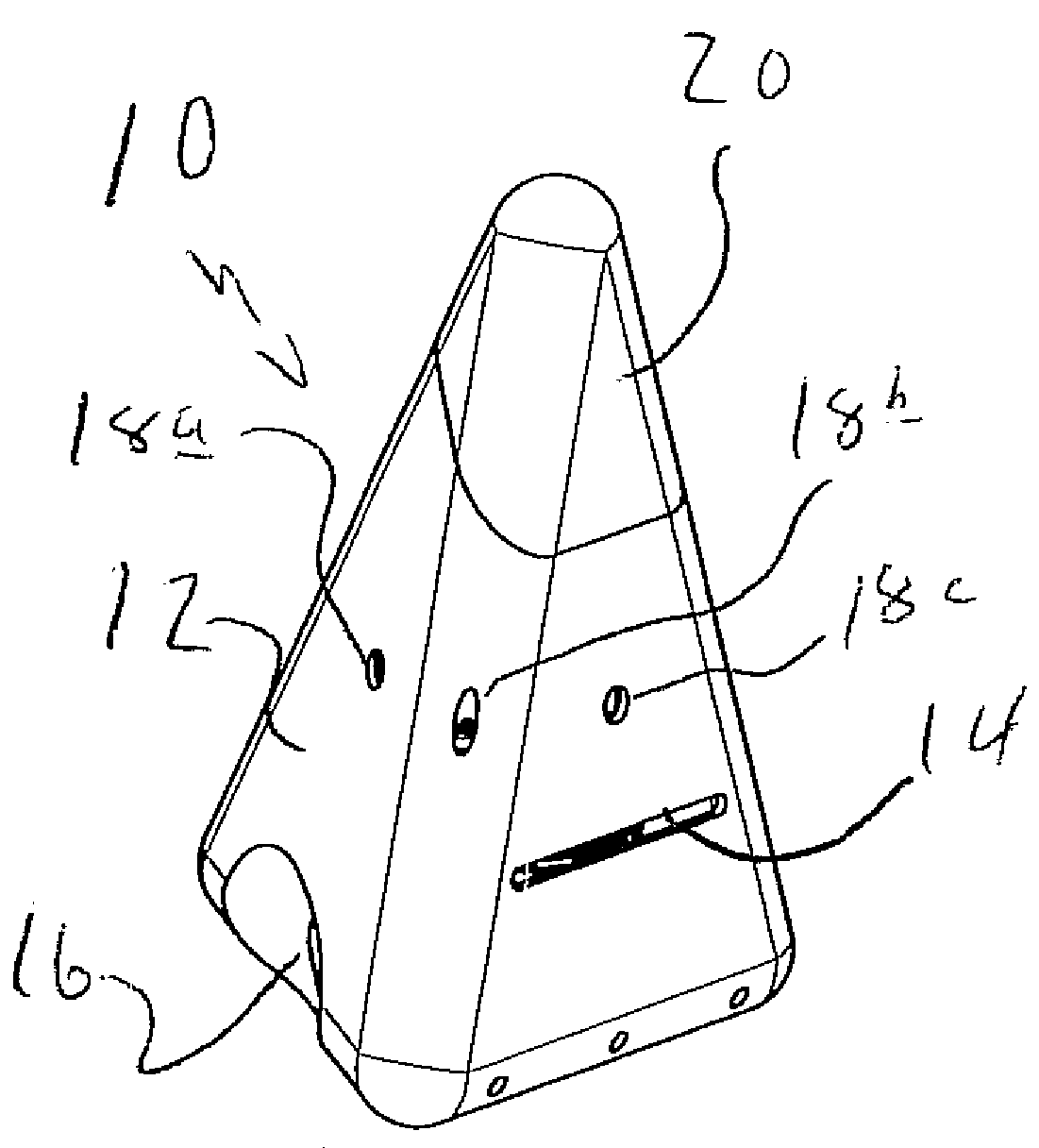
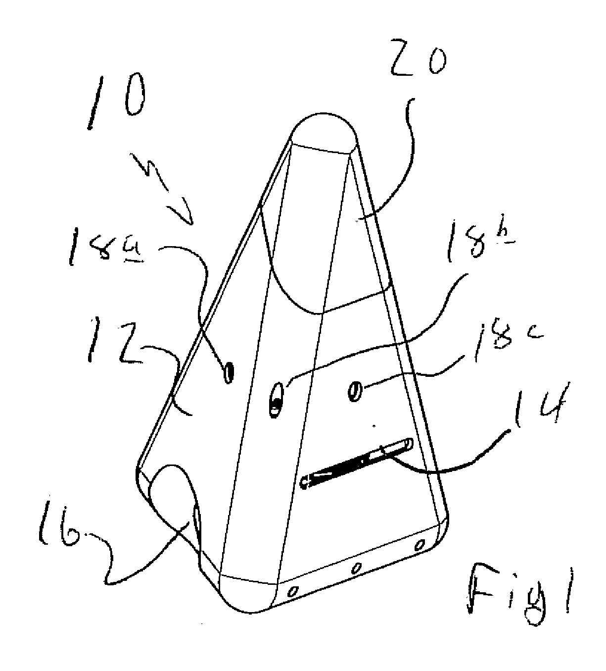
[0016]Referring now to FIG. 1, there is shown a perspective view of one embodiment of electronic candle 10. This candle 10 is configured in a general tetrahedral shape simulative of a pillar-type candle. The candle 10 includes a housing having a main body portion 12. Generally, this portion of the housing will be fabricated from an opaque material, and in particular instances the ma...


PUM

PropertyMeasurementUnit
volatileaaaaaaaaaa
poweraaaaaaaaaa
thermal massaaaaaaaaaa

Abstract

An electronic candle includes a source of light which provides a spatially and temporally varying pattern of illumination which simulates a candle flame, a volatile release station which operates to release a volatile material such as an aromatic material from a cartridge, and a forced convection system which disperses the volatile material. The candle further includes a controller which coordinates the operation of the release of the volatile material and the light source so that the pattern of light produced by the source is coordinated with an attribute of the volatile material being released.

Description

CROSS-REFERENCE TO RELATED APPLICATIONS[0001]This application claims priority of U.S. Provisional Patent Application Ser. No. 60 / 822,244 filed Aug. 13, 2006, entitled “Cordless Portable Electronic Candle Providing Interactive Mood Enhancing Ambient Light and Scent Distribution.”FIELD OF THE INVENTION[0002]This invention relates generally to electrical illumination devices. More specifically, the invention relates to electrical illumination devices which are simulative of a burning candle and which are further operative to dispense a scent or other volatile material.BACKGROUND OF THE INVENTION[0003]Candles have long been used as a source of illumination. In addition, it has been known to incorporate volatile materials such as scents, odor neutralizing materials and the like into candles so that these volatile materials will be released as the candle is burned. The soft light emitted by a burning candle has a pleasant and tranquilizing effect, and this effect is further enhanced in th...

Claims


Application Information

Patent Timeline
Patent Type & Authority Applications(United States)
IPC IPC(8): A61L9/03A61L9/00
CPCA01M1/2072A61L2209/12A61L9/03A01M1/2077
Inventor JARAMILLO, JAMISON
Owner JARAMILLO JAMISON
Why Eureka
Try Eureka