Magnetic induction charged candle

a rechargeable lamp and magnetic induction technology, which is applied in the direction of lighting support devices, lighting and heating apparatus, and with built-in power, can solve the problems of inability to charge indirectly, not only space occupation, but also cost-inefficiency,

Inactive Publication Date: 2007-09-27
HSU WAN CHANG
View PDF6 Cites 68 Cited by
  • Summary
  • Abstract
  • Description
  • Claims
  • Application Information

AI Technical Summary

Benefits of technology

[0015] After combination of the candle and the holder, place the holder onto the charger, the rechargeable batteries of the candle and the holder can be recharging by magnetic induction, which is produced between the electromagnetic coils inside the charger and the holder. (According to the Farady's Law)
[0016] Both of the candle and the holder are portable emitting light devices, when the holder is detached from the candle, each of them can emit light respectively, or they can e...

Problems solved by technology

However, the battery pack (120) depicted in FIG. 8 in the U.S. Pat. No. 6,479,965 at least 3 nickel-cadmium (hereinafter abbreviated as Ni-Cad) batteries was depicted to supply power to the lamp system, this battery pack was not only space-occupied, but also co...

Method used


Image

  • Magnetic induction charged candle
  • Magnetic induction charged candle
  • Magnetic induction charged candle

Examples


Embodiment Construction

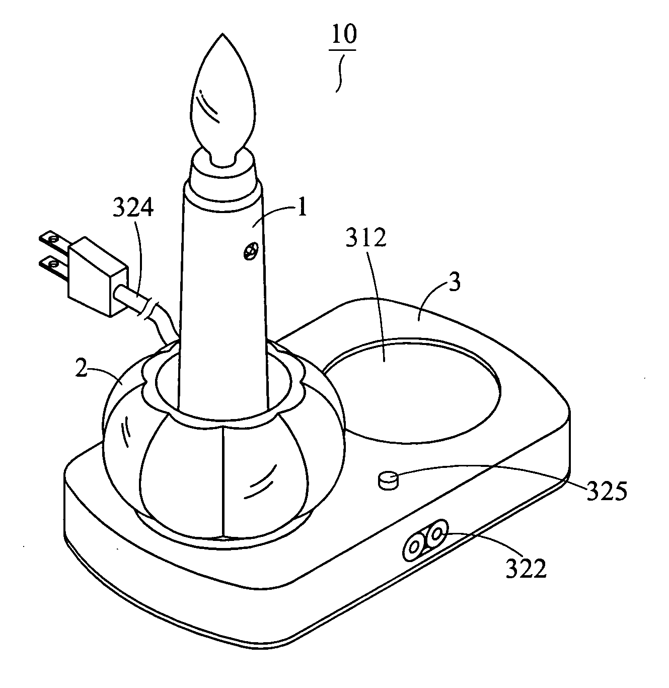
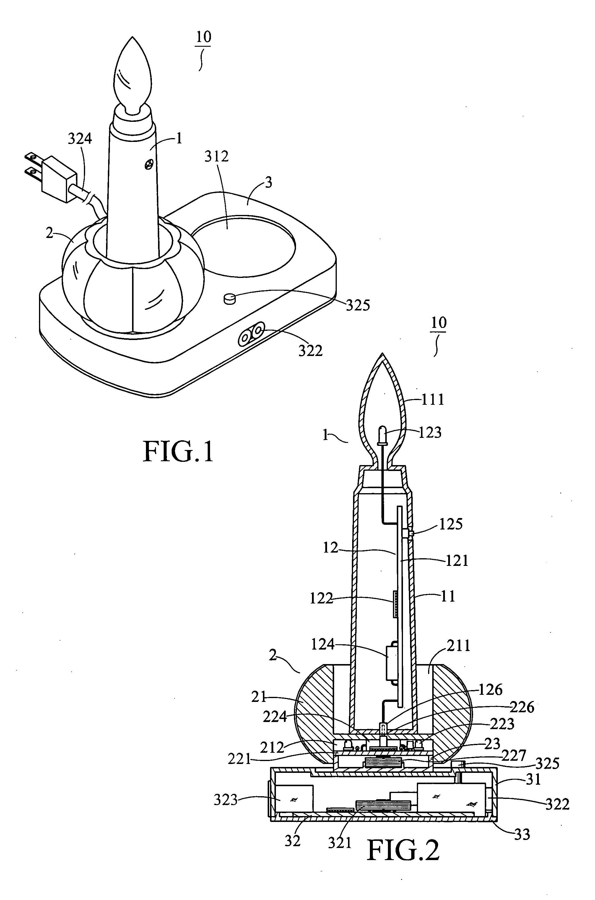
[0024] As shown in FIG. 1, the magnetic induction charged lamp device is combined as a whole illustrated with an assembled view. The lamp device 10 includes a candle 1, a holder 2, and a charger 3.

[0025] As shown in FIG. 2, a cross sectional view along the profile of the PCB of the magnetic induction charged lamp device is illustrated. Candle 1 having a housing 11 consists of a diffuser 111 shaped like a fume, a luminary 12 mounted inside the housing 11. The luminary 12 includes a PCB 121, an IC 112 installed to the PCB 121, a LED 123 attached to a distal end of an angled wire, the proximal end of the wire is fixed to the higher portion of PCB121, the wire first extended from the PCB 121 horizontally and then bended at a right angle to extend upward, the LED 123 on the distal end of the wire is located above the PCB 121, batteries 124 mounted on the PCB 121, a switch 125 on the PCB 121 controlling the power supply, and a wire having a proximal end fixed to the lower portion of PCB ...


PUM


Abstract

A magnetic induction charged candle includes candle, holder and charger. Said candle and holder are equipped with printed circuit board (PCB), integrated circuit (IC), light emitting diode (LED), battery, switch, and terminal respectively. In that, the terminals can be coupled with each other. Thereby, the candle can be combined and mounted to the holder. At the bottom end of the holder has an electromagnetic coil corresponding to an electromagnetic coil inside the charger. When the holder is place into the charger, an electromotive force is produced between the two electromagnetic coils to induce currents. Thereby, the candle and the holder can be charged at the same time. Even the candle and the holder are not equipped with power line, they can be charged with full capacity of electricity. Moreover, the chargers can be in connection with one another in-line to expand the charging capacity.

Description

FIELD OF THE INVENTION [0001] The present invention is related to a magnetic induction rechargeable lamp device resembling a candle. BACKGROUND OF THE INVENTION [0002] Smoke of the conventional candle is filled with carbon dioxide to foul the air; normally a conventional candlelight is flickered by a gust of wind. To improve this defect, persons skilled in the art have provided electronic candle such as TWM 216,183 entitled “Outdoor Electronic Candle” assigned to Wang, Ker-Kwang on Nov. 11, 1993, in which, Wang taught an electronic “fume” with high brightness, which is suitable for an outdoor lighting system. Or as TWM 240,516 entitled “Structure of Electronic Candle” assigned to Jenesis International Inc. on Aug. 11, 2004, in which, an electronic “fume” can be flickered under oscillation of 2˜3 frequencies. And a photosensitive switch on the printed circuit board can activate light emitting diode (hereinafter abbreviated as LED) in surrounding darkness. Or as U.S. Pat. No. 6,479,96...

Claims


Application Information

Patent Timeline
IPC IPC(8): F21L4/00
CPCF21L4/08F21S6/001F21S9/02F21V23/02F21W2121/00H02J7/0027H02J7/0042F21V23/005F21Y2101/02F21Y2115/10H02J7/0044H02J7/0013H02J2310/22
Inventor HSU, WAN-CHANG
Owner HSU WAN CHANG
Why Eureka
Try Eureka