
Universal switch control apparatus

a control apparatus and switch technology, applied in the direction of emergency power supply arrangements, testing/monitoring control systems, instruments, etc., can solve the problems of insufficient function of communication devices that can use wired networks, rare and simple establishment of communication facilities, and high cos

Inactive Publication Date: 2008-09-18
NATIS COMM CORP
View PDF5 Cites 25 Cited by
  • Summary
  • Abstract
  • Description
  • Claims
  • Application Information

AI Technical Summary

Benefits of technology

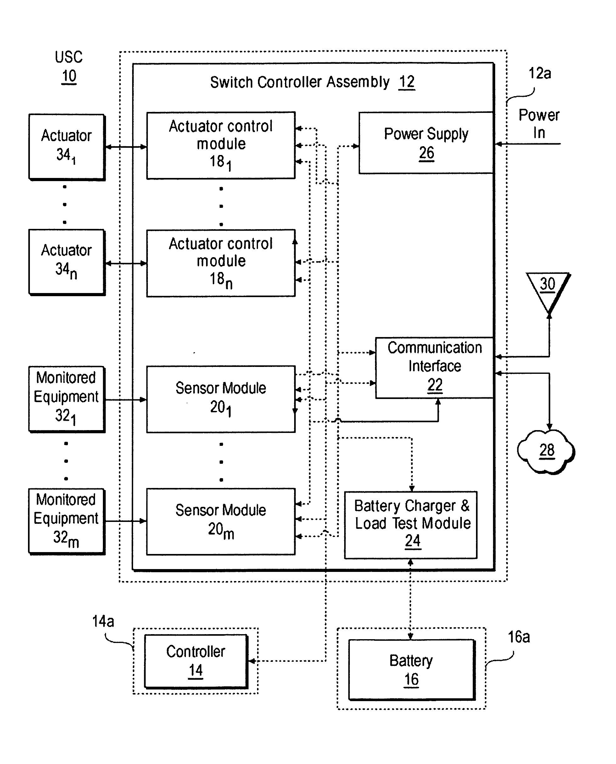
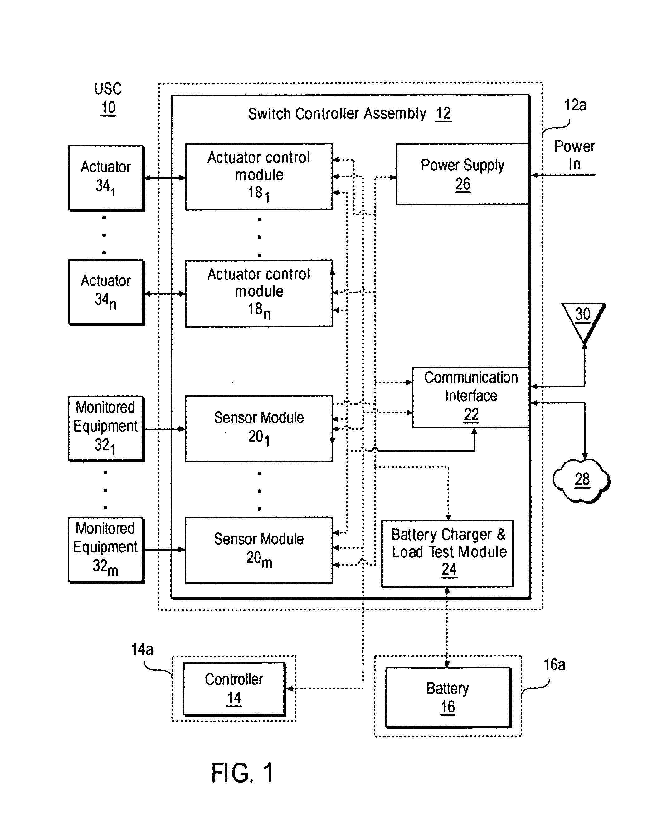
[0012]Various embodiments of the present invention provide an equipment controller that includes one or more actuator control modules, each configured for connection to an actuator which provides operational control of a respective piece of monitored equipment; one or more sensing modules, each configured to monitor a state of a parameter associated with each piece of monitored equipment; an optional control interface communicatively coupled and configured to permit local operator control of the actuator control modules and the sensing modules; and a secondary power system configured to provide operational power for the actuator control modules, the sensing modules and the control interface when primary power to the equipment controller is not available, and which includes a load test system for determining whether the secondary power system is capable of operating under operational load conditions. The actuator control modules and sensor modules may be contained in a housing separate from that in which the control interface is contained. Preferably, these housings are water tight housings, permitting operations of the equipment controller even when fully submerged in water. The equipment controller (or modules thereof) may be installed in or on one or more of: underground vaults, ground level cabinets, or overhead utility poles.
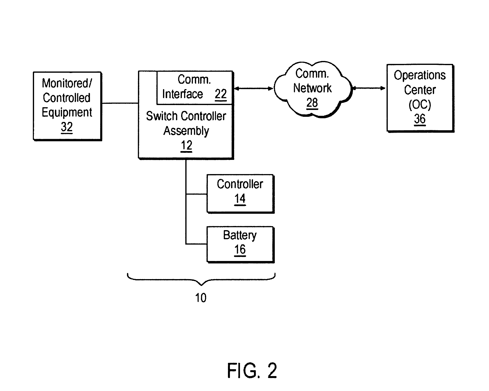
[0013]The secondary power system may be a battery and may include a charging system configured to maintain a sufficient charge in the battery to permit the battery to provide operational power for the actuator control modules, the sensing modules and the control interface when primary power to the equipment controller is not available. At least portions of the secondary power system (e.g., the battery, which may be replaceable) may be contained in a separate, water tight housing from that in which other modules of the controller are contained.
[0014]The equipment controller may also include a communications interface adapted for communications with an operations center remote from the equipment controller. Such communications may be wireless communications, communications over fiber optic networks, communications over cellular communications networks and / or communications over one or more computer networks. In some cases, communications interface may be communicatively coupled to an antenna configured for installation at grade-level.
[0015]Where present, the control interface may be configured as a handheld unit adapted for use outside of a vault in which a housing that includes one or more of the actuator control modules and / or one or more of the sensing modules is located. The control interface may be further configured to indicate status of the monitored equipment parameters and / or control of the actuators.

Problems solved by technology

When the remote equipment is located in underground vaults, however, establishing communication facilities are rarely so simple.
Very few wireless communications networks are designed to work at or below ground level, and most of the communication devices that can use wired networks are not designed to function while fully submerged in water.
Hence, such installations are typically expensive and, when being installed, can cause inconvenience to motorists and pedestrians.
However even when comparing two equivalently rated switches from different manufacturers, the actuators and / or motors which operate the switches may not function in the same fashion.

Method used


Image

  • Universal switch control apparatus
  • Universal switch control apparatus
  • Universal switch control apparatus

Examples


Embodiment Construction

[0022]Described herein is a switch control apparatus (referred to below as a universal switch controller or USC) and a related system in which this apparatus finds particular use. To avoid the above-described costs and drawbacks associated with the use of electrical distribution equipment and similar installations, various embodiments of the present USC are configured to reside entirely underground (e.g., in a vault) with the distribution equipment being monitored or controlled. Other embodiments of the present USC are suitable for use with above-ground and / or overhead equipment.

[0023]Embodiments of the present USC are configured to provide both communication and automation functions for the distribution equipment being monitored and / or controlled. Like the equipment it is associated with, the present USC can be completely submerged in water and still function. Additionally, the present USC is configured to interoperate with distribution equipment of multiple vendors while presentin...


PUM


Abstract

An equipment controller includes an actuator control module configured for connection to an actuator that provides operational control of a piece of monitored equipment; a sensing module configured to monitor a state of a parameter of the monitored equipment; an optional local control interface for the actuator control module and the sensing module; and a secondary power system to provide operational power for the actuator control modules, the sensing modules and the control interface when primary power to the equipment controller is not available. Where desired, a communications interface to permit communications with a remote operations center may be included. Some or all of the modules may be contained in water tight housings, permitting operation of the equipment controller even when fully submerged in water.

Description

RELATED APPLICATIONS[0001]This is a NONPROVISIONAL of, claims priority to and incorporates by reference, U.S. Provisional Patent Application 60 / 887,118, filed 29 Jan. 2007.FIELD OF THE INVENTION[0002]The present invention relates to an apparatus for monitoring and controlling electric power distribution equipment located above grade, in ground-level cabinets or in underground vaults, and suitable for, but not limited to, use with Supervisory Control and Data Acquisition (SCADA) systems.BACKGROUND[0003]Modern utility (natural gas, water, electricity, etc.) services are increasingly being provided through distribution networks located underground. Indeed, many municipalities and other governmental organizations now require that any new installations of such distribution means be made solely through underground equipment. Thus, while utility poles and overhead electrical lines were once a common site in many cites, such cables are now being placed below grade and the associated distrib...

Claims


Application Information

Patent Timeline
Patent Type & Authority Applications(United States)
IPC IPC(8): H02J9/06
CPCG05B9/02H02J9/06G05B23/0256
Inventor FREEMAN, MITCHELL B.HARRIS, EDEE M.
Owner NATIS COMM CORP
Learn More