
Device and method of supplying power to targets on single-wire interface

Active Publication Date: 2008-12-04
ATMEL CORP
View PDF21 Cites 25 Cited by
  • Summary
  • Abstract
  • Description
  • Claims
  • Application Information

AI Technical Summary

Benefits of technology

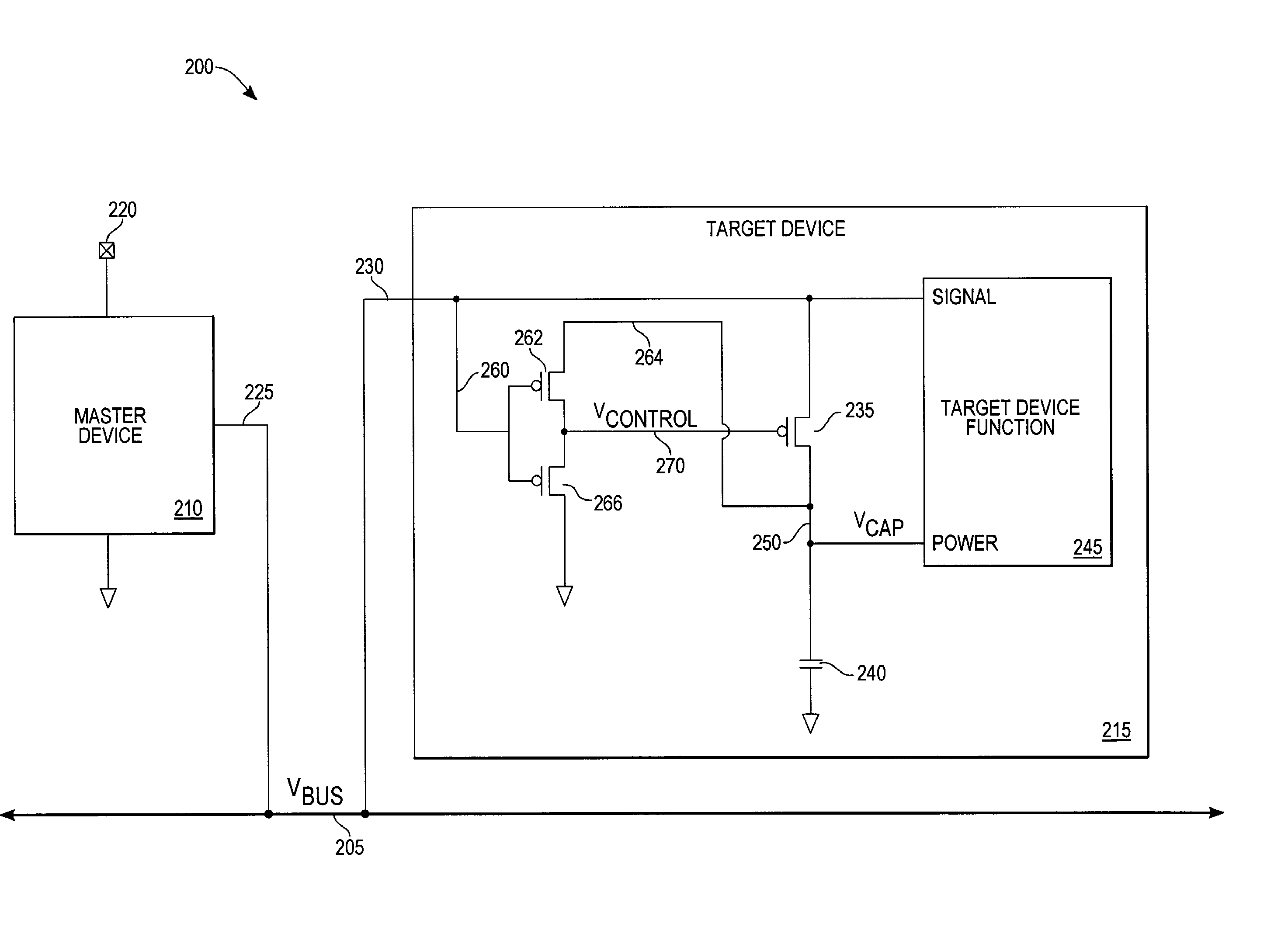
[0010]An exemplary embodiment of a single-wire-interface system comprises a single-wire interface capable of providing electrical communication of signals and power between a plurality of devices coupled to the single-wire interface, including a master device driving the single-wire interface to communicate signals on that interface and maintaining a power supply voltage level on the interface during non-communication time periods, and a target device coupled to the interface device coupled to the interface to receive signals therefrom, wherein the target device includes a PMOS transistor acting as a switch coupled at its source to the single-wire interface, a charge storage device coupled to a drain of the PMOS transistor at a connection point, a device function coupled to the charge storage device at the connection point to receive stored power therefrom, and an inverter acting as a control device with an input coupled to the interface, a control output coupled to the gate of the PMOS transistor, and powered by the charge storage device at the connection point. The use of a PMOS transistor to couple the charge storage device to the interface allows full charging of the connection point to the power supply voltage level during non-communication time periods.

Problems solved by technology

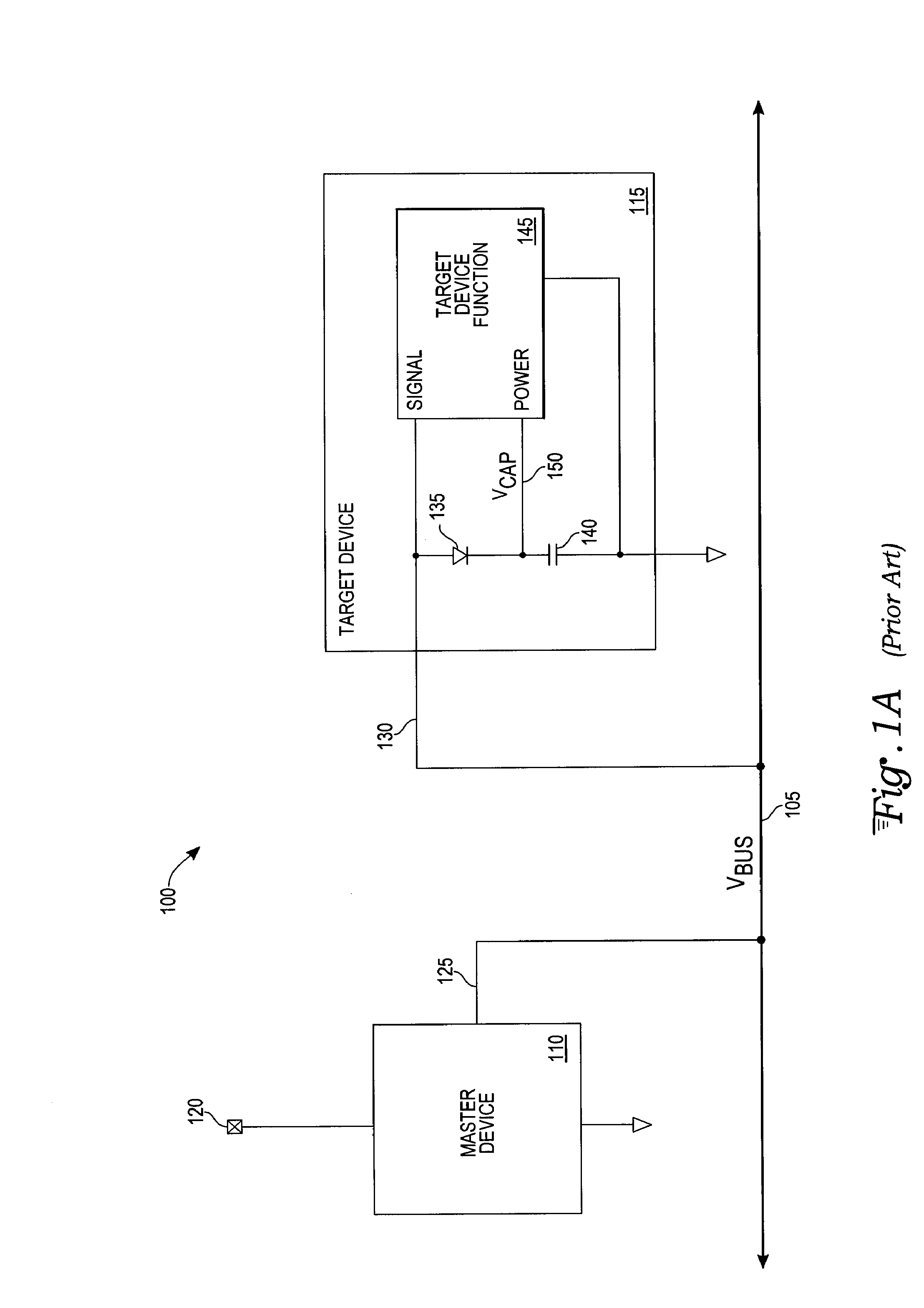
The lack of effectiveness of a complex bus may be due to either cost or a system constraint, such as area for routing a bus, as may be the case in a vehicle.
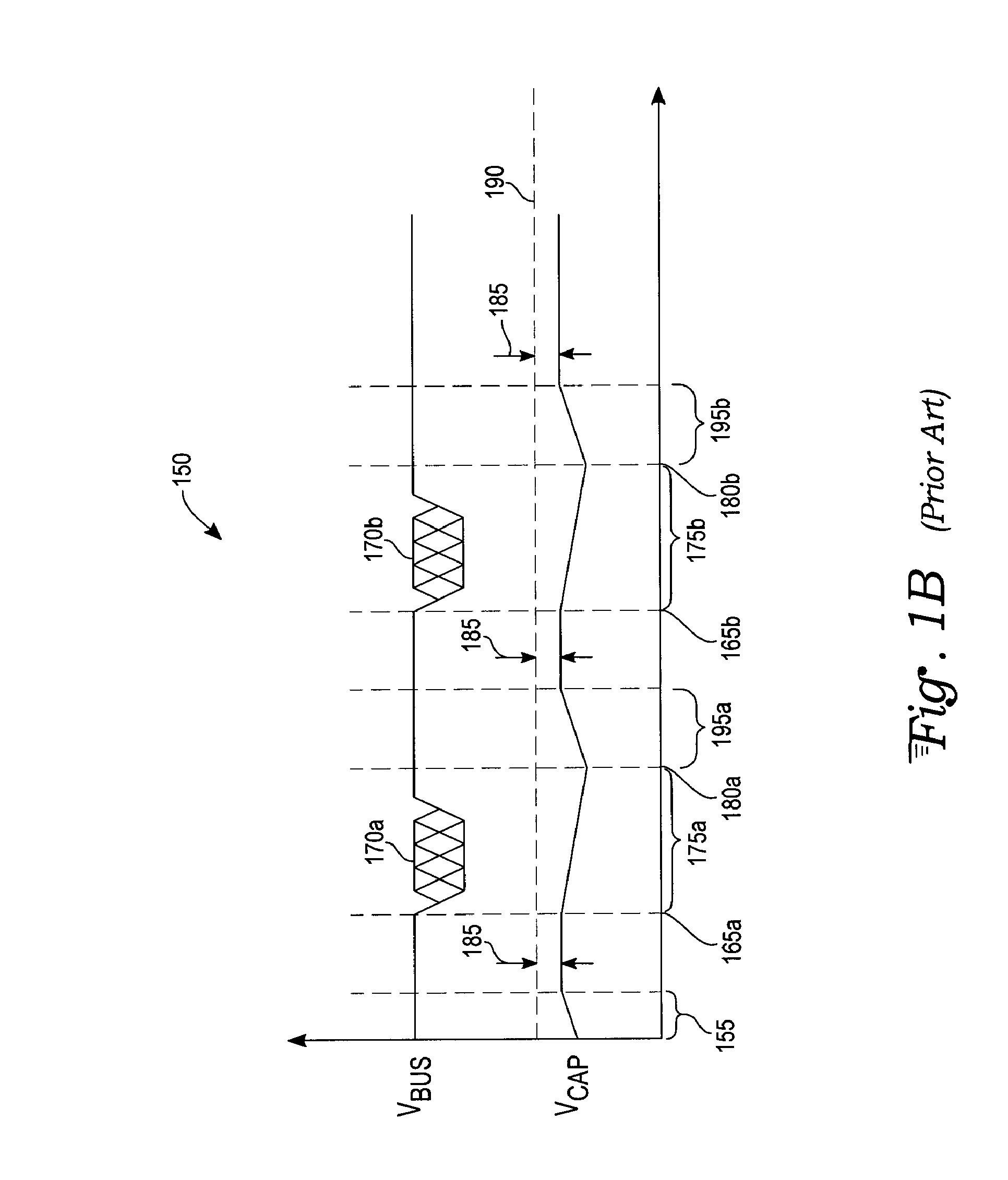
Even with a longest period of time required for recharging the capacitor 140, there is still a significant drawback in that the recharge voltage level achieved is at one diode forward bias voltage drop 185 below the power supply voltage 190 provided on the single-wire interface 105.
In a low voltage system, this amount of voltage drop 185 may mean that the available voltage level remaining to power target device functions may not be sufficient for proper operation of those functions or for the requisite duration.

Method used


Image

  • Device and method of supplying power to targets on single-wire interface
  • Device and method of supplying power to targets on single-wire interface
  • Device and method of supplying power to targets on single-wire interface

Examples


Embodiment Construction

[0015]With reference to FIG. 2A, a single-wire interface 205 couples a master device 210, such as a microcontroller, to a target device 215 in an exemplary single-wire-interface system 200. A single-wire interface 205 is alternately known as a single-wire data bus, one-wire data bus, unibus, or a one-wire interface. A single wire is shared in common by all of the devices attached to the single-wire interface 205. The single-wire interface 205 implements a one-wire protocol by which bus level transactions across one wire communicate the signaling required both to control and power a target function.

[0016]The single-wire interface 205 connects devices of a system together to perform desired functions. In a general system context, a master device 210, such as a microcontroller, may alternately be referred to as a transmitter or an initiator controller, while the target device 215 may alternately be referred to as a receiver, a slave, or a target controller.

[0017]The master device 210 i...


PUM


Abstract

A single-wire interface communication system is capable of providing both electrical communication of signals and power between devices coupled to the system. Coupled to the single-wire interface is at least one target device which contains a PMOS transistor, a charge storage device, an inverter controlling the PMOS transistor, and a target device function. The charge storage device provides power to the target device function and to the inverter. The PMOS transistor receives power from the single-wire interface at a power-supply voltage level and charges the charge storage device to the same level. Non-communication periods produce a charging period sufficient for the charge storage device to attain the power-supply voltage level.

Description

TECHNICAL FIELD[0001]The present invention relates to single-wire interfaces, more particularly, to single-wire interfaces where a target device is supplied with both signals and power over the single-wire interface.BACKGROUND ART[0002]A single-wire interface plays an important part in communicating between devices where a complex bus structure is not effective. The lack of effectiveness of a complex bus may be due to either cost or a system constraint, such as area for routing a bus, as may be the case in a vehicle. A single wire bus is able to provide signaling to implement a bidirectional protocol between bus elements and power to a target device.[0003]With reference to FIG. 1A, a single-wire interface 105 couples a master device 110 to a target device 115 in a prior art single-wire-interface system 100. The master device 110 is coupled to an external power supply VDD 120 and ground, and to the single-wire interface 105 via a line 125. The master device 110 may transmit a signal ...

Claims


Application Information

Patent Timeline
IPC IPC(8): H04L12/413
CPCH04L12/40032H04L12/40045H04L2012/40273
Inventor NG, PHILIP S.YE, KEN
Owner ATMEL CORP
Learn More