Light with simulated candle flicker

a technology of flickering lights and candles, applied in the field of lighting, can solve the problems of inability to produce realistic flickering lights, prior art devices are costly to construct or unreliable to operate, etc., and achieve the effects of convenient adjustment, low cost, and low cos

Inactive Publication Date: 2005-08-09
CHIEN LUEN INDS
View PDF10 Cites 66 Cited by
  • Summary
  • Abstract
  • Description
  • Claims
  • Application Information

AI Technical Summary

Benefits of technology

[0011]The above described apparatus and method substantially improve upon the prior art by providing an inexpensive and reliable way of simulating the flicker of a candle flame. The use of a resistive and capacitive circuit to control the frequency of oscillation of the lights is less expensive than prior methods and allows for the flicker of the light to be easily adjusted for various applications. Furthermore, the use of independently oscillating light sources produces a realistic candle like flicker that varies over time. The use of LEDs is beneficial in that they have extremely low power requirements, eliminate the need for a microcontroller, are inexpensive and last much longer than standard incandescent bulbs. Furthermore, the use of LEDs makes certain embodiments of the present invention particularly well adapted for use in solar powered landscaping lights. Therefore, the present invention is a substantial improvement upon the prior art.

Problems solved by technology

Unfortunately, many of these devices fail to produce a realistic flickering light.
Furthermore, the prior art devices tend to be costly to construct or unreliable to operate.

Method used


Image

  • Light with simulated candle flicker
  • Light with simulated candle flicker
  • Light with simulated candle flicker

Examples


Embodiment Construction

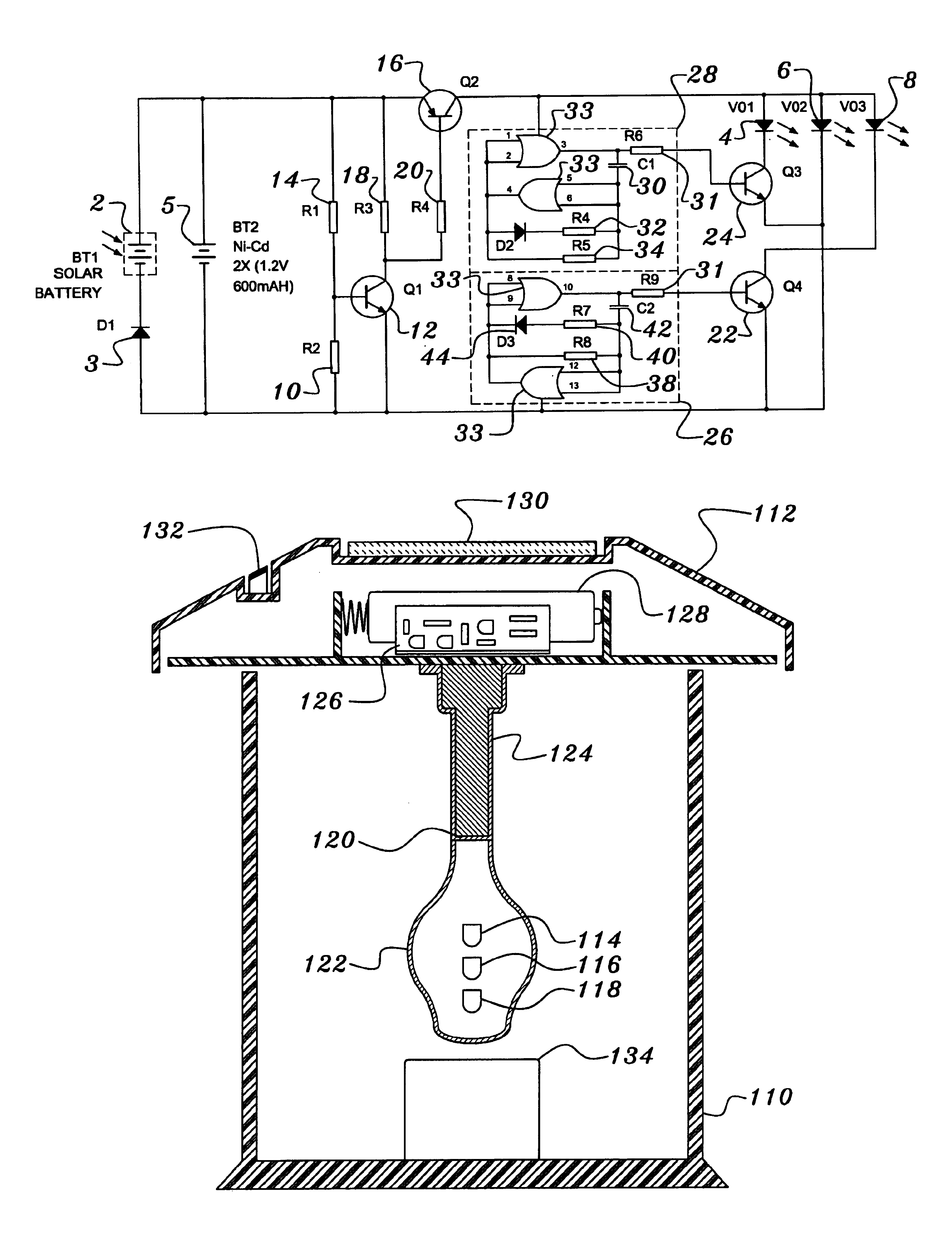
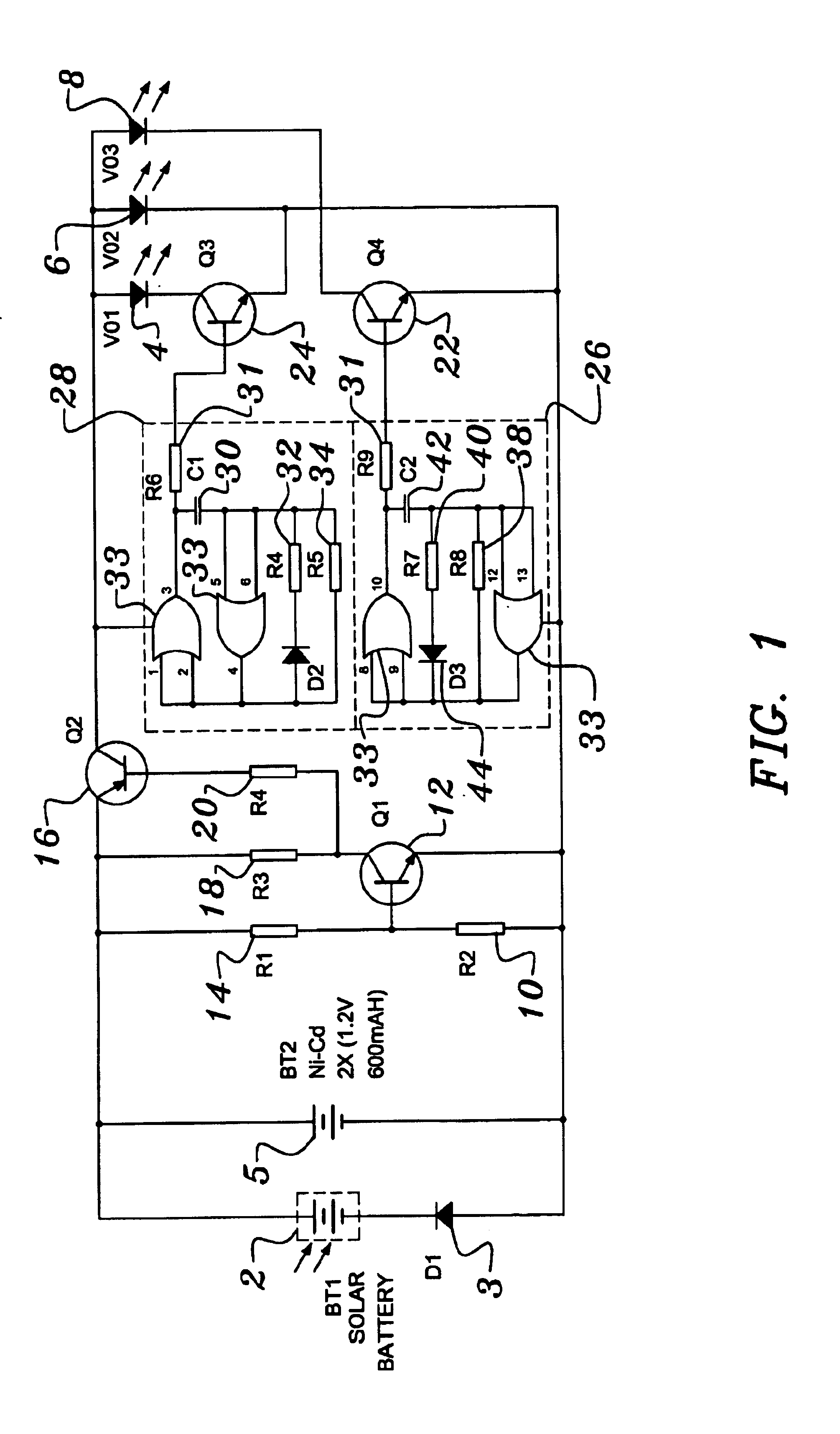
[0020]Referring now to FIG. 1, a schematic of a candle flicker circuit constructed in accordance with a preferred embodiment of the present invention is shown. The preferred embodiment is powered by a solar panel 2 and an associated rechargeable battery 5. A solar panel 2 and battery 5 are particularly useful when utilizing the present invention in an outdoor application such as landscape lighting as they eliminate the need to run power wires to each of the lights. A diode 3 prevents a reverse current from flowing through the solar panel 2 and battery 5. The solar panel 2 and associated battery 5 are used to provide power to the candle flicker circuit and its three light emitting diodes (“LEDs”) 4, 6 and 8. LEDs are preferably used due to their relatively long useful life spans and their low power requirements. However, it will readily appreciated by those skilled in the art in view of the present disclosure that a variety of different types of light sources such as incandescent, et...


PUM


Abstract

A device and system for simulating the flicker of candle flame is provided by the present invention. A series of independent charging and discharging circuits are provided that produce power waveforms having duty cycles that vary from a highest duty cycle to a lowest duty cycle. The power waveforms are provided to a series of LEDs arranged in a vertical stack. The lowest duty cycle power waveform is provided to the highest LED in the stack and the highest duty cycle power waveform is provided to the lowest LED in the stack. An approximately flame shaped housing that is partially translucent is positioned around the vertical stack of LEDs such that the light from the LEDs is visible while the LEDs themselves are not. A solar panel and an associated rechargeable battery are used to power the device.

Description

FIELD OF THE INVENTION[0001]This invention generally relates to the field of lighting. More particularly, the present invention is directed toward a light that simulates the flickering of the flame of a candle.BACKGROUND OF THE INVENTION[0002]Presently, there are a number of different lighting systems for simulating the light produced by a burning object such as a candle flame. Unfortunately, many of these devices fail to produce a realistic flickering light. Furthermore, the prior art devices tend to be costly to construct or unreliable to operate. Therefore, it is an object of this invention to substantially improve upon the prior art by providing an improved lighting device and process for producing a realistic, candle-like flickering light that is inexpensive to construct and reliable and efficient to operate.[0003]Therefore, it is an object of this invention to provide an improvement which overcomes the aforementioned inadequacies of the prior art devices and provides an improv...

Claims


Application Information

Patent Timeline
Patent Type & Authority Patents(United States)
IPC IPC(8): H05B33/02H05B33/08F21S10/04H05B44/00
CPCF21S10/04H05B33/0803H05B33/0818H05B33/0824Y10S362/80Y10S362/806Y10S362/81F21Y2101/02F21K9/23F21Y2115/10H05B45/44H05B45/00H05B45/12
Inventor BUCHER, JOHN C.BUCHER, CHARLES E.
Owner CHIEN LUEN INDS
Why Eureka
Try Eureka