Wind powered devices

Inactive Publication Date: 2008-02-21
KURTZ WILLIAM C
View PDF0 Cites 22 Cited by
  • Summary
  • Abstract
  • Description
  • Claims
  • Application Information

AI Technical Summary

Benefits of technology

[0012] In a variant of the invention, wind devices are located in locations where there is a relatively large amount of wind. For example, wind devices may be placed on cars, trucks, busses, trains, ships, bicycles or airplanes so that as they move, the wind generated by their movement in addition to any naturally occurring land, if any, may be used to turn windmills to provide the benefits described above.

Problems solved by technology

Obviously this is a large amount of energy, most of which is not converted into other forms of usable energy.

Method used


Image

  • Wind powered devices
  • Wind powered devices
  • Wind powered devices

Examples


Embodiment Construction

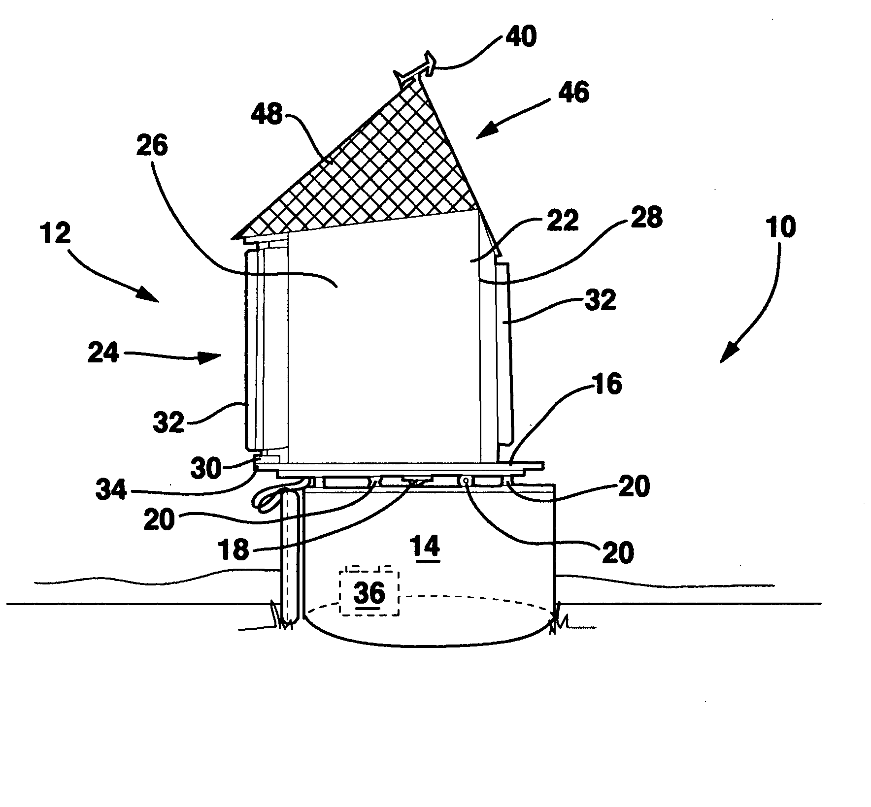
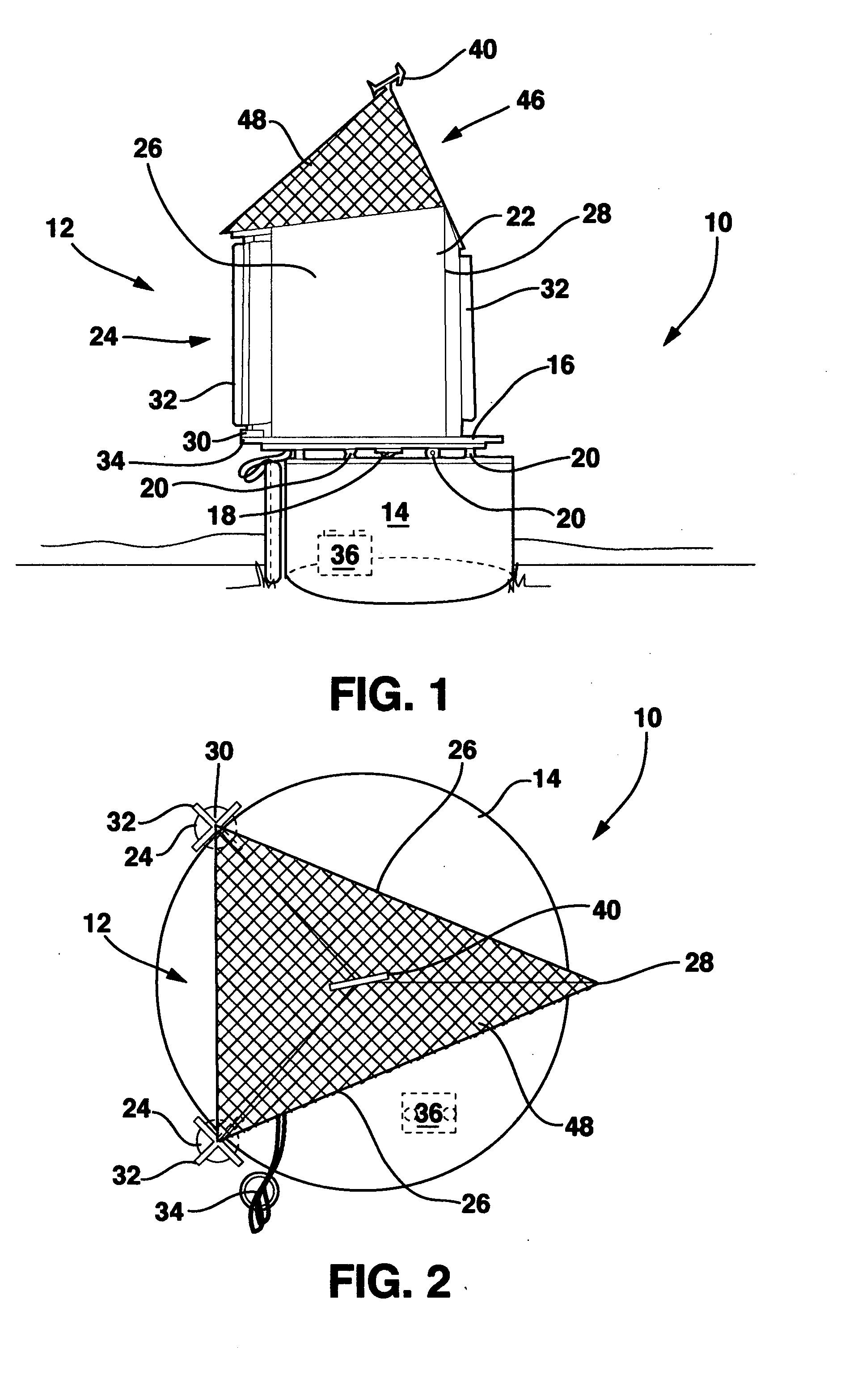
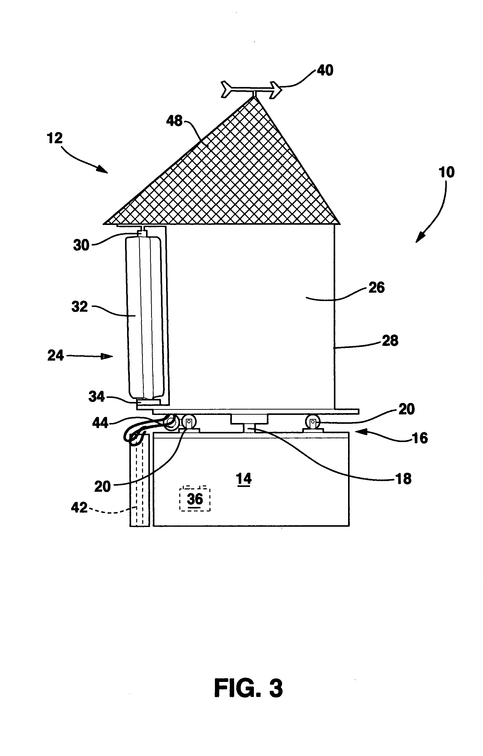
[0035] In order that the invention may be clearly understood and readily carried into effect, preferred embodiments of the invention will now be described, by way of example only and not to limit the invention, with reference to the accompanying drawings. The wind devices of the present invention are shown in the drawings generally labeled 10.

[0036] The wind device 10, in an embodiment shown in FIGS. 1-3, includes a wind collector 12 and a support structure 14. Wind collector 12 interacts with the wind to capture energy from the wind do a desired task as will be explained hereafter. Support structure 14 provides a base and a support for the wind collector 12 and places the wind collector 12 in contact with the wind. As such, support structure 14 can have many sizes, shapes and configurations so long as the support structure 14 securely supports and places the wind collector 12 in a position to be contacted by and interact with the wind.

[0037] For example, in the embodiment of the ...


PUM


Abstract

Devices for converting wind energy into other usable forms of energy are disclosed. In one embodiment of the invention, a wind device having at least one but more preferably two vertically directed cylindrical windmills are disposed on the ends of a “V” shaped structure so that half of each windmill is exposed to contact by the wind moving along the outer surface of the “V” as the point of the “V” is aimed into the wind. In this configuration, the other half of each windmill is located within the “V” shaped structure where this half does not come into contact with the wind. As a result, the wind contacting the outside half of each windmill causes the windmill to rotate. Each rotating windmill is mechanically connected to a device to convert the rotation of the windmills into another form of energy. In a variant of this embodiment, the vanes are located a distance from the axis of rotation in order to generate more torque in light winds. In another variant of the invention, wind devices are located in locations where there is a relatively large amount of wind such as on cars, trucks, busses, trains, ships, bicycles or airplanes, near on or in tunnels or near the ends of runways so that propeller blast or jet wash from departing aircraft may be captured by the invention and converted into usable energy as described above.

Description

BACKGROUND OF THE INVENTION [0001] 1. Field of the Invention [0002] This invention relates to devices for converting wind energy into other usable forms of energy. [0003] 2. Description of Related Art [0004] It is estimated that 1% to 3% of solar energy that hits the Earth is converted naturally into wind energy. This is about 50 to 100 times more energy than is converted into biomass by all the plants on Earth through photosynthesis. Obviously this is a large amount of energy, most of which is not converted into other forms of usable energy. [0005] Most of this wind energy is found at high altitudes. However, some of the wind is found close to the Earth's surface. Over the years, many devices have been developed that convert this wind energy found close to the Earth into other forms of usable energy. For example, windmills have been developed that convert wind energy into mechanical energy that is used to crush grain or pump water. [0006] Relatively recently, wind energy has been c...

Claims


Application Information

Patent Timeline
IPC IPC(8): H02P9/04F03D9/00
CPCB60L8/00B63J3/04B63J2003/046F03D3/0445B60L2200/26Y02E10/74Y02T10/7083Y02T70/70F03D9/002F03D9/25Y02E10/50Y02T10/7072Y02T70/00Y02E70/30F03D9/20F03D9/28F03D9/11F03D3/0454F03D9/007F03D3/02H02S10/12
Inventor KURTZ, WILLIAM C.
Owner KURTZ WILLIAM C
Why Eureka
Try Eureka