
Sterilizer for baby products

a technology for sterilizing products and baby products, which is applied in the field of sterilizing products for baby products, can solve the problems of increasing the volume of products to carry, drying of baby products and breast feeding supplies, and scalding babies

Inactive Publication Date: 2008-02-21
ESENCIA
View PDF57 Cites 4 Cited by
  • Summary
  • Abstract
  • Description
  • Claims
  • Application Information

AI Technical Summary

Benefits of technology

[0010]An object of the present invention is to provide a sterilizer for baby products that can keep the baby products and breast feeding supplies simply, conveniently and sanitarily by including first and second cases provided with UV generating means disposed at one side thereof and a storage space formed therein to keep the baby products and breast feeding supplies therein, placing means disposed in any one of the first and second cases, and coupling means to which a neck of a bottle is coupled at any one of the first and second cases, wherein the baby products and breast feeding supplies, such as a nursing bottle, are coupled and fixed to the coupling means in the storage space of the first and second cases in a home or in particular when a parent / parents goes / go out of doors, and the baby products including the nursing bottle are sterilized by ultraviolet rays radiated from the UV generating means.

Problems solved by technology

However, the conventional method has a problem in safety that babies may be scalded by the boiling water and a problem that in the natural drying, contaminants contained in the air may be adsorbed on the baby products or breast feeding supplies to cause a secondary infection.
However, the above method also has a problem that the baby products and breast feeding supplies may be secondarily infected by other products dried in the dish drier, for example, dishes for adults.
Meanwhile, when a parent / parents goes / go out of doors with infant and / or babies, it is essentially required to carry the sterilized baby products and break feeding supplies in an amount necessary for the going out time, which increases the volume of the products to carry, thus limiting the parent(s) from going out doors.
In addition, after all the baby products or breast feeding supplies carried for going out of doors have been used, the used baby products or breast feeding supplies have to be again used, which is insanitary.

Method used


Image

  • Sterilizer for baby products
  • Sterilizer for baby products
  • Sterilizer for baby products

Examples


first embodiment

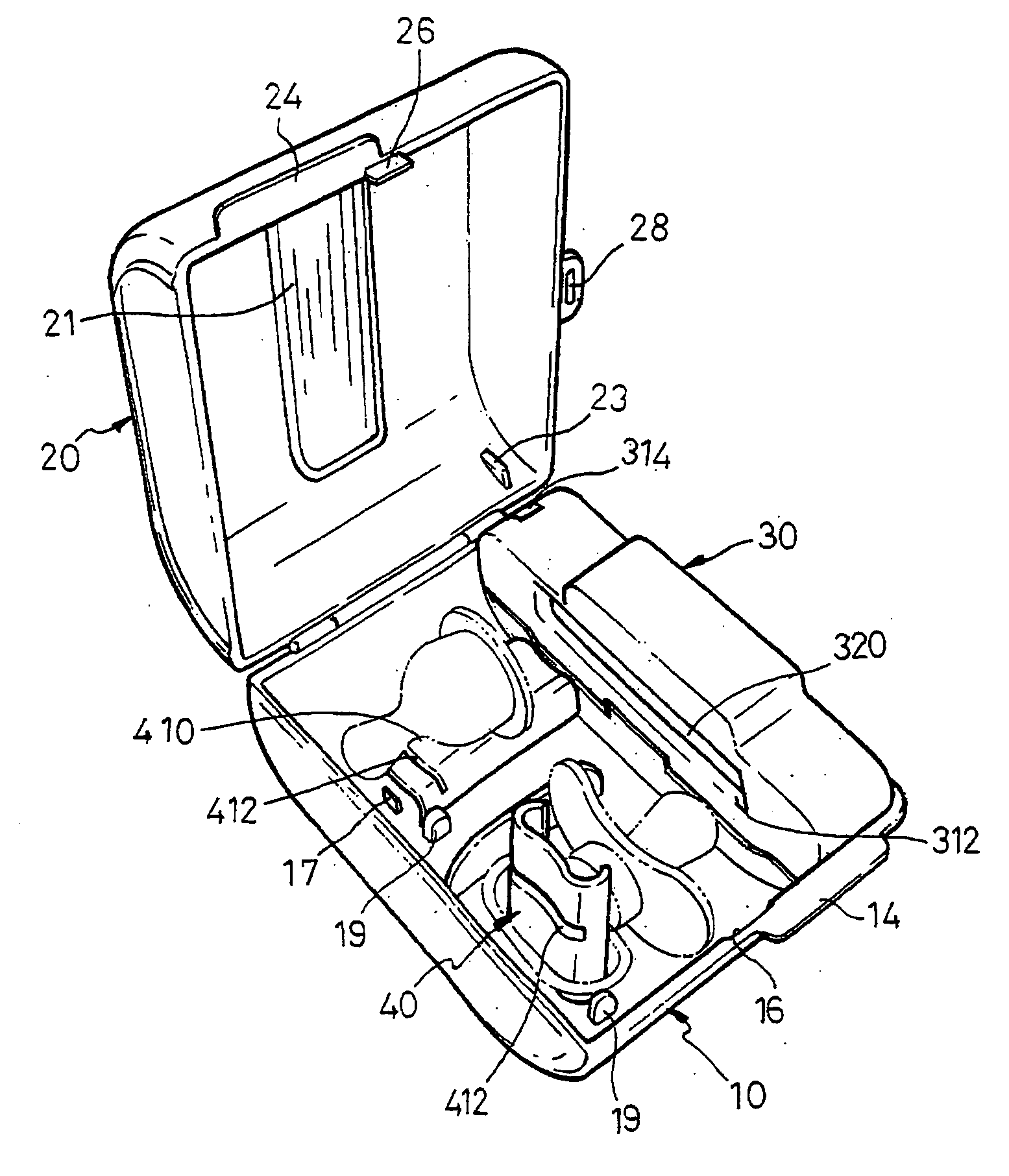
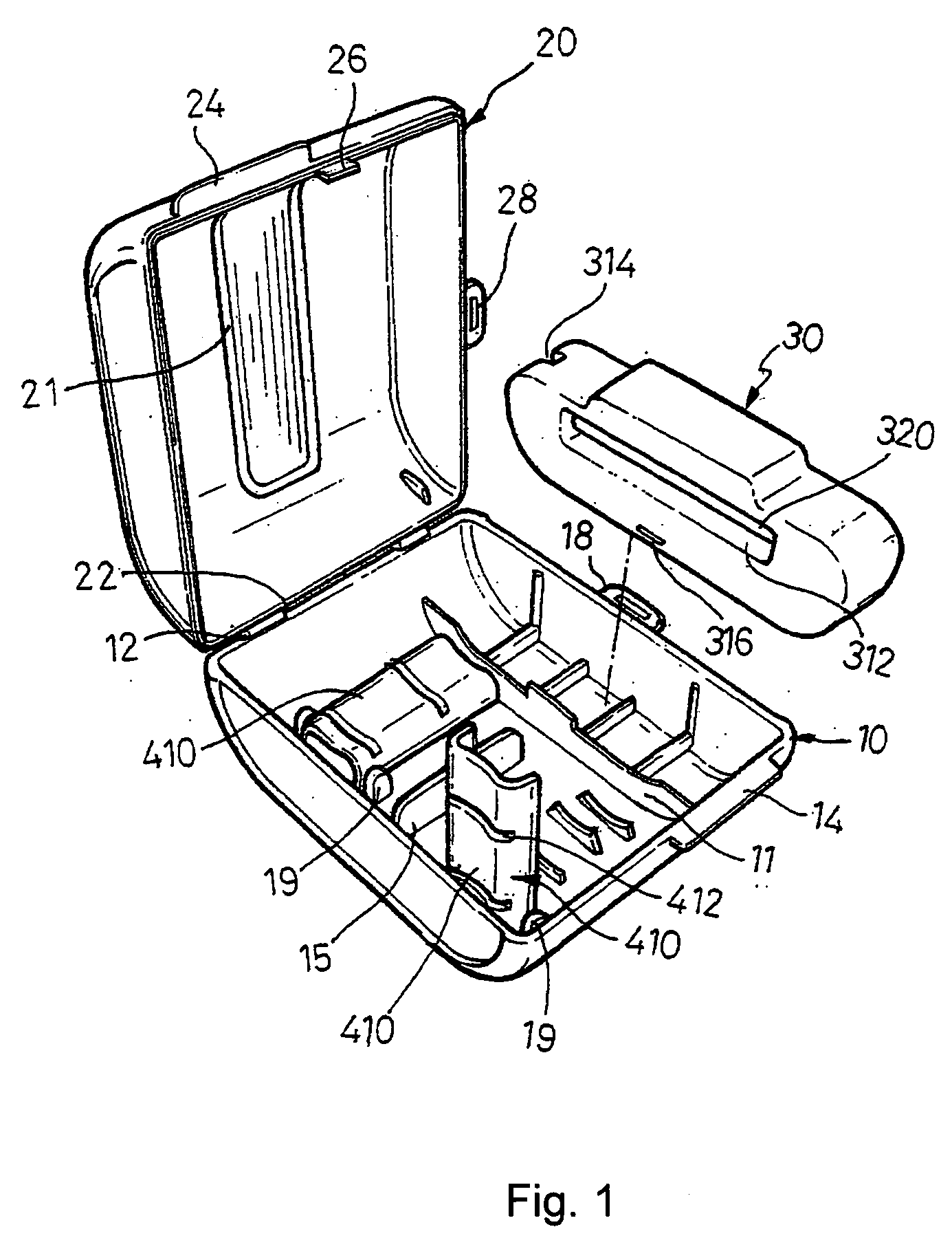
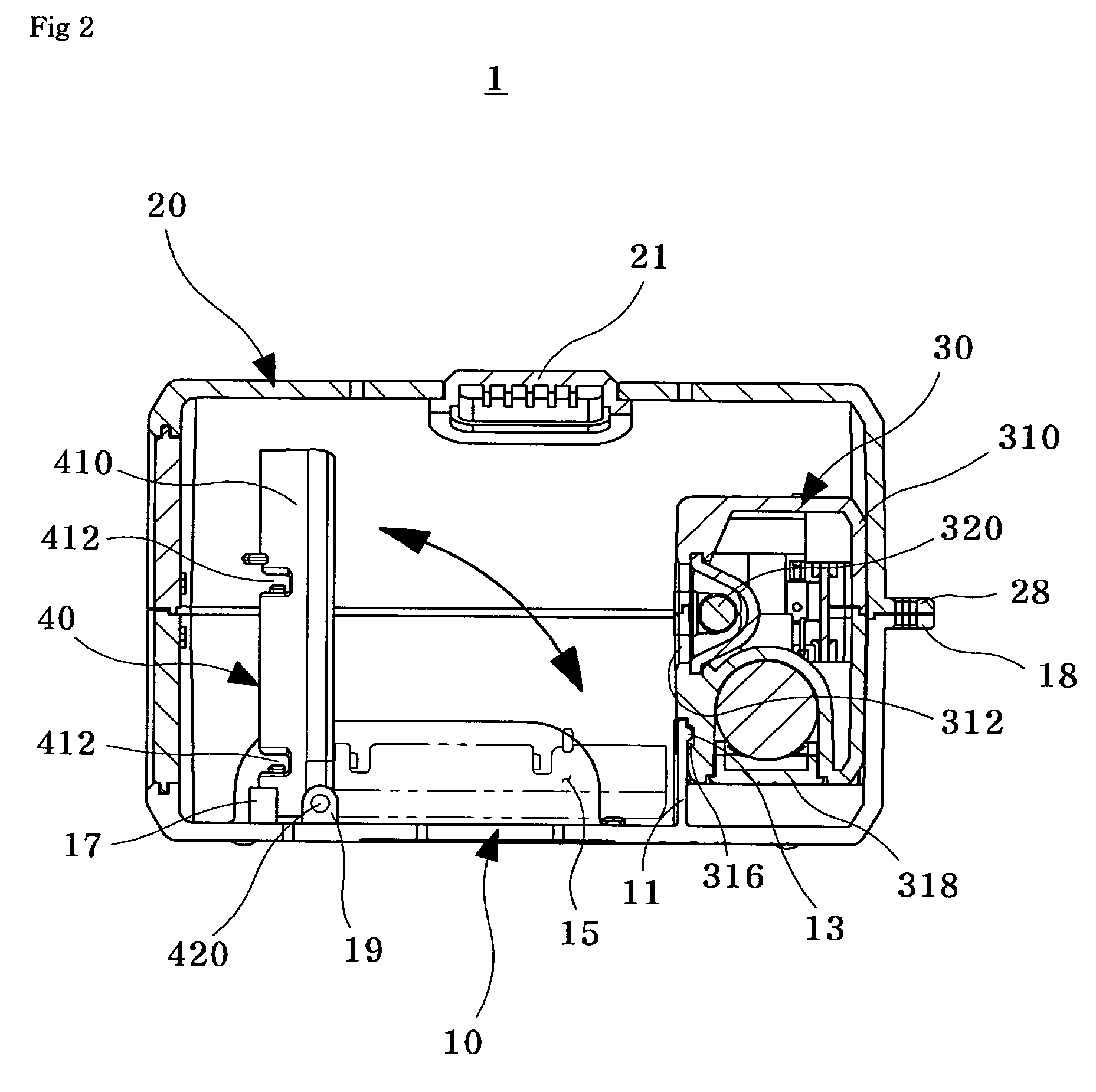
[0029]FIG. 1 is a partial disassembled perspective view of a sterilizer for baby products according to a first embodiment of the present invention, and FIG. 2 is a sectional view of FIG. 1.

[0030]Referring to FIGS. 1 and 2, a sterilizer 1 for baby products includes first and second cases 10 and 20 each having a storage space therein and that can be relatively opened and closed, UV generating means 30 provided in the storage spaces of the first and second cases 10 and 20, and placing means 40.

[0031]The UV generating means 30 and the placing means 40 can be disposed in the first case 10 and a window 21 for viewing an inside of the second case can be formed of a transparent material in the second case 20. However, it is preferable that the window 21 is formed of a semi-transparent material such that light is transmitted by half of light emitting when a sterilization lamp of the UV generating means 30 is turned on to amplify the design of the baby products using a light scattering.

[0032]...

second embodiment

[0062]FIG. 5 is a partial disassembled perspective view of placing means according to a second embodiment of the present invention, and FIG. 6 is a sectional view showing a usage of the placing means according to the second embodiment of the present invention. Referring to FIGS. 5 and 6, unlike in the first embodiment that described the placing means fixed in the first case, in the second embodiment, the placing means is a sliding means that slides along the floor of the first case. Like reference numerals are used to denote like elements described in the First Embodiment, and repetition of detailed descriptions of these elements are omitted herefrom.

[0063]The sliding type placing means 40a includes a placing bar 410 forming a placing space 414 within, a plurality of placing slots 412 formed in a lengthwise direction, and hinge protrusions 420 protruding from either side thereof. A sliding member 430 includes hinge receptacles 432 provided at an upper portion thereof for respectivel...

third embodiment

[0071]FIG. 7 is a perspective view showing a usage of the placing means according to a third embodiment of the present invention. Like reference numerals are used to denote like elements described in the First Embodiment, and repetitions of detailed descriptions of these elements are omitted herefrom.

[0072]Referring to FIG. 7, a placing means according to the third embodiment of the present invention includes a placing bar 510 with a gripping recess 512 recessed a predetermined distance in a central, upper portion thereof, and a coupling protrusion (not shown) protruding at the bottom of the placing bar 510.

[0073]Also, an insertion slot 19b is formed in a lengthwise direction along the floor of the first case 10, allowing the coupling protrusion (not shown) of the placing bar 510 to be detachably inserted therein.

[0074]Accordingly, a placing bar 510 of the placing means may be erected by inserting the coupling protrusion protruding from the lower portion thereof into any one of the ...


PUM


Abstract

The present invention relates to a sterilizer for baby products that can sterilize, safekeep and sanitizes relatively small-sized baby products and minimize the baby products from being lost. The sterilizer for baby products of the present invention includes: first and second cases (10, 20) each having a storage space therein and a hinge member (12, 22) formed at one edge thereof and into which a shaft is inserted such that the first and second cases (10, 20) are rotatably opened and closed around a shaft; UV generating means provided at any one of the storage spaces of the first and second cases (10, 20); and placing means provided in the storage spaces of the first and second cases (10, 20) to fix the baby products.

Description

BACKGROUND OF THE INVENTION[0001]1. Field of the Invention[0002]The present invention relates to a sterilizer for baby products that can sterilize and sanitizes relatively small-sized baby products and minimize the baby products from being lost.[0003]2. Description of the Related Art[0004]Generally, since infants or babies have a low immunity, it is required to always sterilize the products used by the infants or babies, for example, nipple, pacifier, device for teeth growth, and a variety of toys, before or after being used.[0005]The baby products and breast feeding supplies are conventionally disinfected by dipping and sterilizing them in a boiling water for a predetermined time and drying them in a natural state. However, the conventional method has a problem in safety that babies may be scalded by the boiling water and a problem that in the natural drying, contaminants contained in the air may be adsorbed on the baby products or breast feeding supplies to cause a secondary infec...

Claims


Application Information

Patent Timeline
IPC IPC(8): A61L2/00
CPCA61L2/10
Inventor SHIN, CHOONG-SIK
Owner ESENCIA
Learn More