Tape head with outrigger

a tape bearing surface and tape head technology, applied in the direction of maintaining the head carrier alignment, manufacturing head surface, instruments, etc., can solve the problems of data not being the spacing between the edges of the tape and the tape bearing surface is increased, and the data cannot be reliably written to the edge of the tap

Inactive Publication Date: 2008-02-28
IBM CORP
View PDF21 Cites 38 Cited by
  • Summary
  • Abstract
  • Description
  • Claims
  • Application Information

AI Technical Summary

Benefits of technology

[0019]In one embodiment of the present invention, the outrigger has a tape bearing surface, wherein a second wrap angle is defined between the plane of the outrigger tape bearing surface and a tape traveling towards the outrigger tape bearing surface. For example, the second wrap angle may be greater than about 0.1° and less than about 2°.

Problems solved by technology

This is a result of air leaking in at the edges and tape mechanical effects.
Particularly, the edges of the tape tend to curl away from the tape bearing surface 109, resulting in edge loss or increased spacing between the edges of the tape and the tape bearing surface 109.
This is undesirable, as data cannot reliably be written to the edges of a tape in a system subject to edge loss.
Additionally, the tape lifting 205 results in additional stress at points 206 which, in turn, may cause additional wear of the head.
However, situations arise where rollers may not be the most desirable choice to set the external wrap angles αo.
Additionally, rollers, and particularly adjustable roller systems, may be more expensive to install in the drive.
A further drawback of this approach is mechanical alignment cannot be completed independent of signal read readiness.
Accordingly, it will not be possible to create and outrigger on the same substrate on which the transducers are formed in the next generation of heads.
Another difficulty created by the reduced span is that the height of the outrigger must be kept to a very tight tolerance to maintain the proper wrap angle, as the shorter distance between outrigger and primary tape bearing surface means there is less room for deviation.

Method used


Image

  • Tape head with outrigger
  • Tape head with outrigger
  • Tape head with outrigger

Examples


Embodiment Construction

[0037]The following description is the best mode presently contemplated for carrying our the present invention. This description is made for the purpose of illustrating the general principles of the present invention and is not meant to limit the inventive concepts claimed herein. Further, particular features described herein can be used in combination with other described features in each and any of the various possible combinations and permutations.

[0038]In the drawings, like and equivalent elements are numbered the same throughout the various figures.

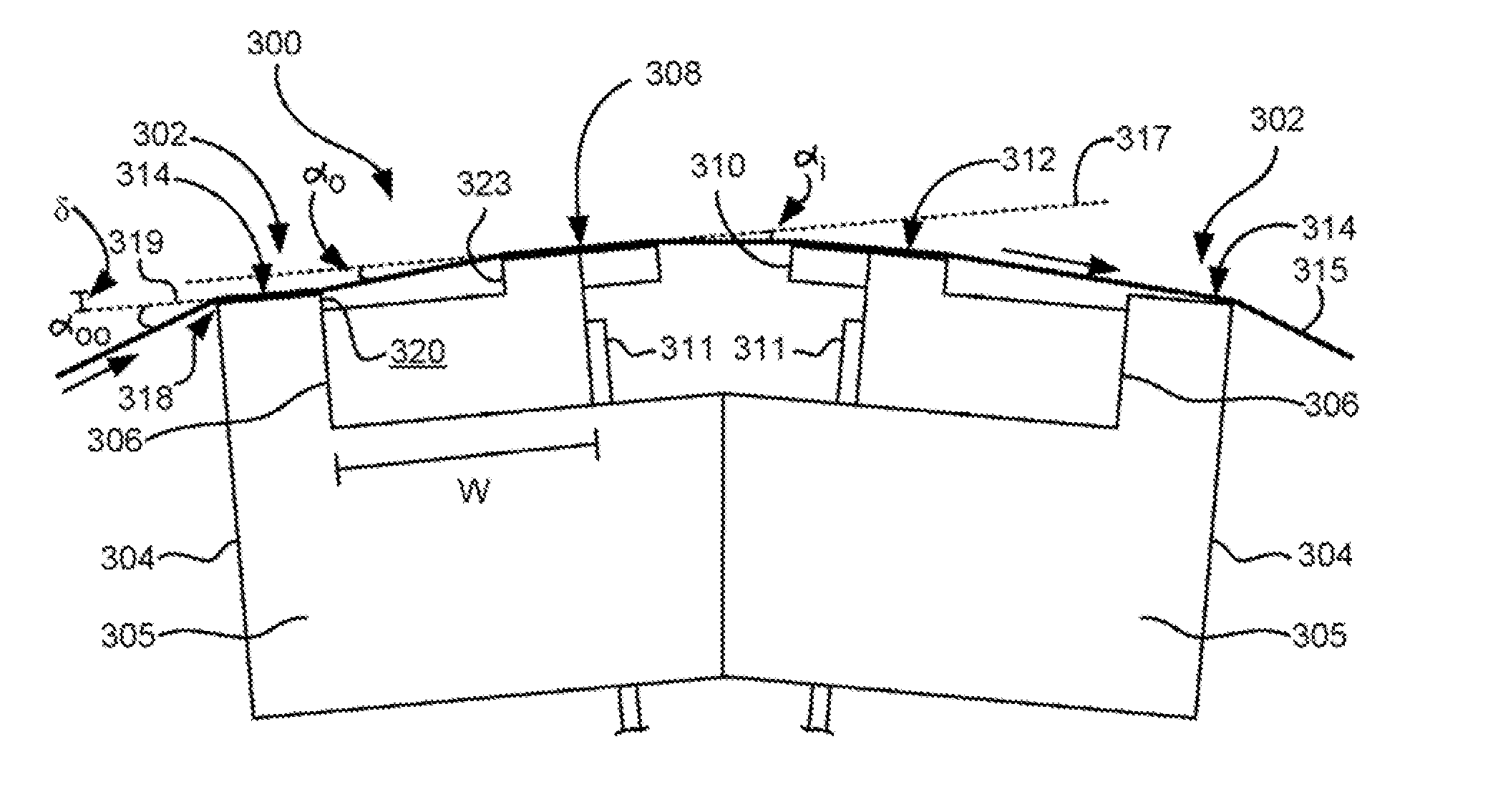
[0039]The embodiments described below disclose a new tape head design the tolerates a wider range of initial tape wrap angles in a drive implementing minute heads without sacrificing drive performance. This is accomplished by equipping the head with a novel type of outrigger, as explained below. The outriggers control the critical wrap angles within the head, and at he same time prevent the ‘external’ variations due to head positioni...


PUM

PropertyMeasurementUnit
thicknessaaaaaaaaaa
thicknessaaaaaaaaaa
wrap angleaaaaaaaaaa

Abstract

A magnetic head assembly according to one embodiment of the present invention includes a substrate having a tape bearing surface. A plurality of elements are coupled to the substrate and positioned towards the tape bearing surface. The elements selected from a group consisting of readers, writers, and combinations thereof. A base is coupled to the substrate. The base has an outrigger formed integrally therewith. The outrigger causes a tape passing thereacross to approach the substrate at a first wrap angle relative to a plane of the tape bearing surface of the substrate.

Description

FIELD OF THE INVENTION[0001]The present invention relates to tape head structures, and more particularly, this invention relates to a tape head structure having an outrigger for establishing a tape wrap angle.BACKGROUND OF THE INVENTION[0002]FIG. 1 illustrates a traditional flat-lapped bi-directional, two-module magnetic tape head 100, in accordance with the prior art. As shown, the head includes a pair of bases 102, each equipped with a module 104. The bases are typically ceramic beams shaped in the form of a U that are adhesively coupled together. Each module 104 includes a substrate 104A and a closure 104B with readers and writers 106 situated therebetween. In use, a tape 108 is moved over the modules 104 along a tape bearing surface 109 in the manner shown for reading and writing data on the tape 108 using the readers and writers 106. Conventionally, a partial vacuum is formed between the tape 108 and the tape bearing surface 109 for maintaining the tape 108 in close proximity w...

Claims


Application Information

Patent Timeline
Patent Type & Authority Applications(United States)
IPC IPC(8): G11B5/00G11B5/187
CPCG11B5/00826G11B5/1872G11B5/60G11B5/255G11B5/3106G11B5/1871
Inventor BISKEBORN, ROBERT GLENNLIANG, JASONLO, CALVIN SHYHJONG
Owner IBM CORP
Why Eureka
Try Eureka