Radio Communication System

a radio communication and system technology, applied in the field of radio communication systems, can solve the problem that the uplink transmission data cannot be sent through each connection at the designated slot, and achieve the effect of improving the radio communication quality

Inactive Publication Date: 2008-03-06
FUJITSU LTD
View PDF11 Cites 36 Cited by
  • Summary
  • Abstract
  • Description
  • Claims
  • Application Information

AI Technical Summary

Benefits of technology

[0021]In view of the foregoing, the present invention has been made. An object of the present invention is to provide a radio communication system that performs control such that data does not collide with each other during transmission and receiving when a relay station performs radio relay communication with a plurality of radio base stations, to improve radio communication quality.

Problems solved by technology

In the above-described conventional networks, where the relay station 1a performs radio relay communication with a plurality of radio base stations, however, the following problems may occur.
In that case, since the relay station cannot send different data to different radio base stations by using the same slot, the uplink transmission data cannot be sent through each connection at the designated slot.

Method used


Image

  • Radio Communication System
  • Radio Communication System
  • Radio Communication System

Examples


Embodiment Construction

[0046]An embodiment of the present invention will be described below by referring to the drawings.

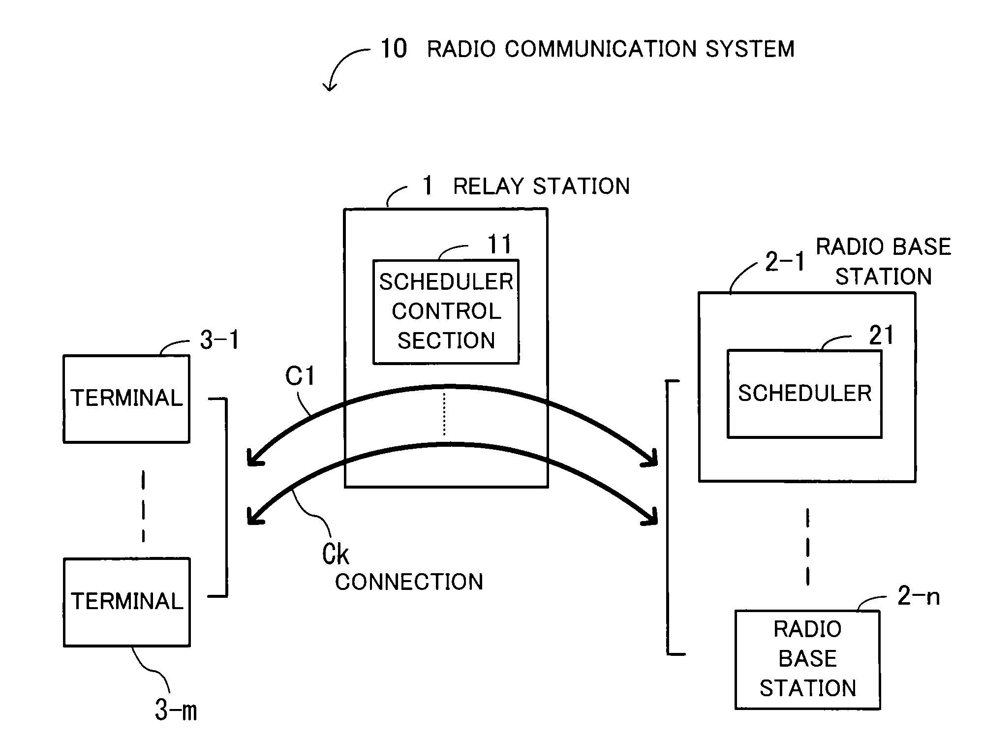
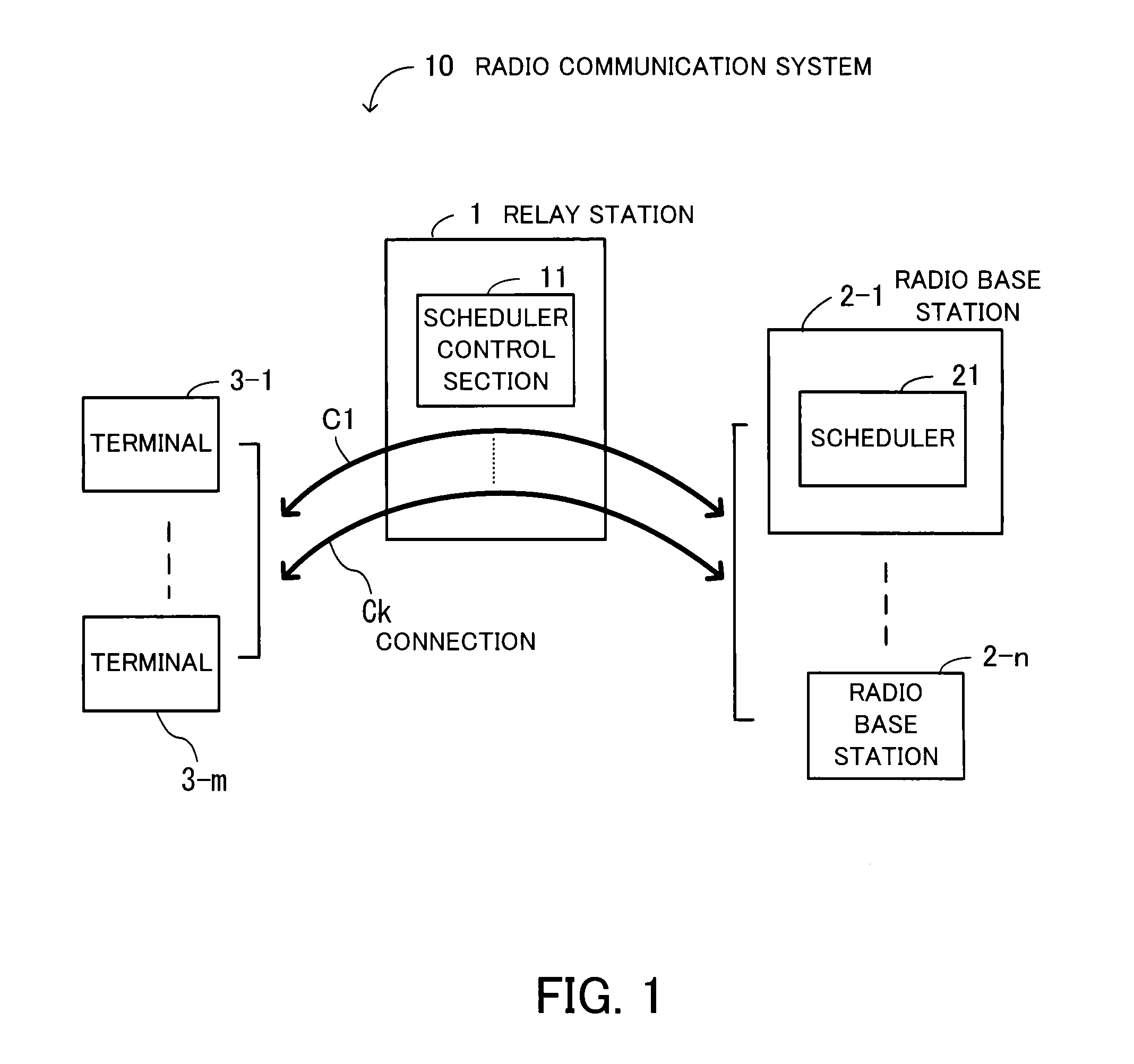
[0047]FIG. 1 shows a principle of a radio communication system 10. The radio communication system 10 is formed of a relay station 1, radio base stations 2-1 to 2-n (collectively called a radio base station 2), and terminals 3-1 to 3-m (collectively called a terminal 3), and performs relay communication by radio.

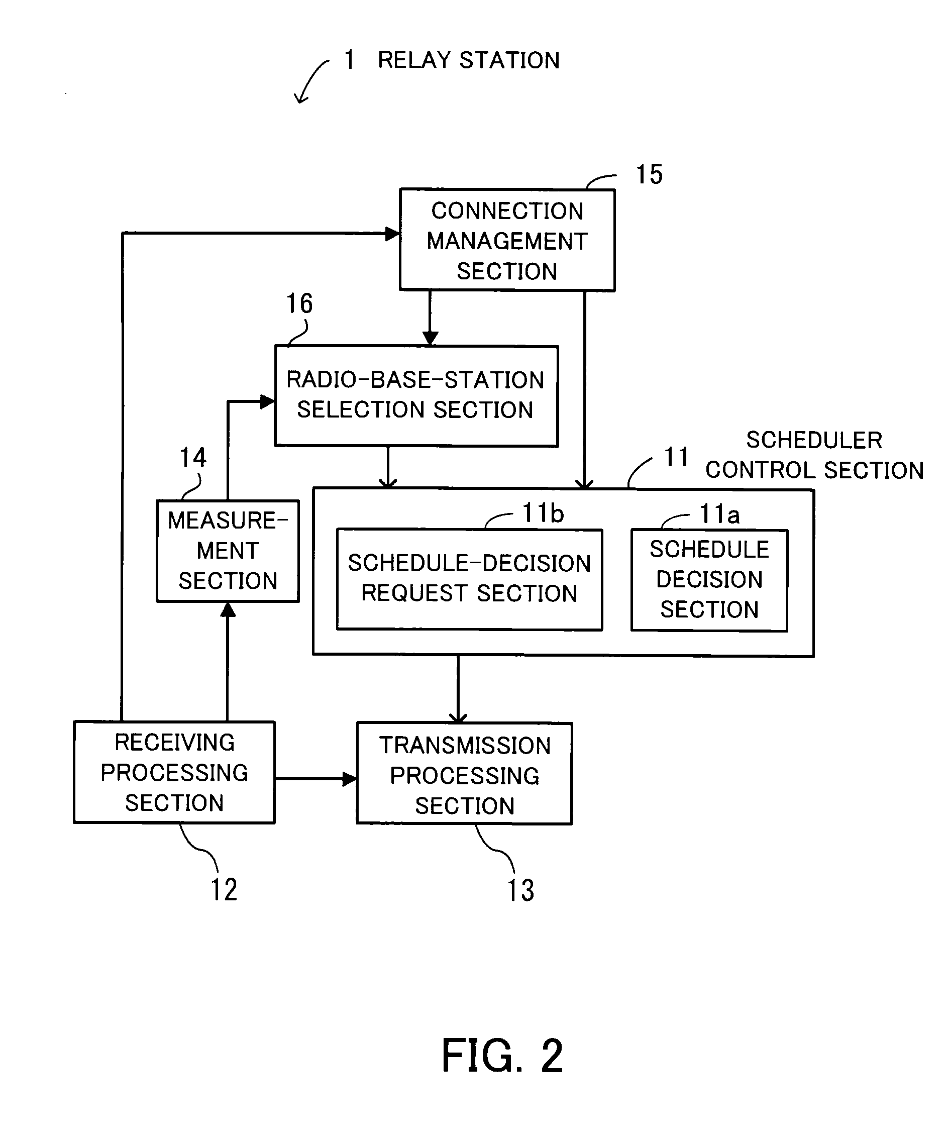
[0048]Each of the radio base stations 2-1 to 2-n includes a scheduler 21. The scheduler 21 arranges a schedule of assignment of a slot into which data is to be inserted, in a radio frame. The terminals 3-1 to 3-m perform communication with the radio base stations 2-1 to 2-n through connections C1 to Ck. The relay station 1 includes a scheduler control section 11 that gives an instruction of the schedule to the scheduler 21, and performs relay forwarding of radio frames exchanged through the connections C1 to Ck.

[0049]The scheduler control section 11 gives an instruction to the sc...


PUM


Abstract

A radio communication system for preventing transmission and receiving data from colliding with each other in radio relay communication. The radio communication system includes a plurality of radio base stations each having a scheduler for arranging a schedule of assignment of a slot into which data is to be inserted in a radio frame, a terminal for performing communication with at least one of the radio base stations through a connection, and a relay station for performing relay forwarding of the radio frame exchanged through the connection, the relay station including a scheduler control section for giving an instruction of the schedule to the scheduler. The scheduler control section gives the instruction to the scheduler so as not to generate duplicate slot assignment, in which the whole or a part of data is assigned to the same slot in radio frames sent at the same timing.

Description

CROSS-REFERENCE TO RELATED APPLICATIONS[0001]This application is based upon and claims the benefits of priority from the prior Japanese Patent Application No. 2006-234767, filed on Aug. 31, 2006, the entire contents of which are incorporated herein by reference.BACKGROUND OF THE INVENTION[0002]1. Field of the Invention[0003]The present invention relates to radio communication systems, and particularly to a radio communication system that performs relay communication by radio.[0004]2. Description of the Related Art[0005]In radio communication systems, communication is generally performed between a terminal and a radio base station connected to an upper network by a wired link. In recent years, systems have attracted attention in which a relay station that performs relay forwarding by radio is introduced between the radio base station and terminal. Since placing the relay station extends a relay possible area, it is possible to extend the communication area and to improve the communic...

Claims


Application Information

Patent Timeline
Patent Type & Authority Applications(United States)
IPC IPC(8): H04B7/14H04B7/15H04W16/02H04W16/26H04W72/04H04W72/12
CPCH04B7/2653H04B7/15542H04W72/1273
Inventor NAKATSUGAWA, KEIICHI
Owner FUJITSU LTD
Why Eureka
Try Eureka