Electric Braking Apparatus and Vehicle Having Thereof

a technology of electric brakes and braking devices, which is applied in the direction of braking components, position/direction control, special data processing applications, etc., can solve the problems of influencing vehicle behavior and unable to detect the contact position of the brake pads

Active Publication Date: 2008-03-06
HITACHI ASTEMO LTD
View PDF13 Cites 34 Cited by
  • Summary
  • Abstract
  • Description
  • Claims
  • Application Information

AI Technical Summary

Benefits of technology

[0008]The pad contacting position can be dete

Problems solved by technology

There is also a problem that, in a case where the pad thermally expands more than the clearance, the pad contacting position might not be detected.
In a method of calculating the pad contacting position from a piston advancing position at a time

Method used


Image

  • Electric Braking Apparatus and Vehicle Having Thereof
  • Electric Braking Apparatus and Vehicle Having Thereof
  • Electric Braking Apparatus and Vehicle Having Thereof

Examples


Embodiment Construction

[0036]A main constitution of an embodiment to which the present invention is applied will hereinafter be described with reference to the drawings.

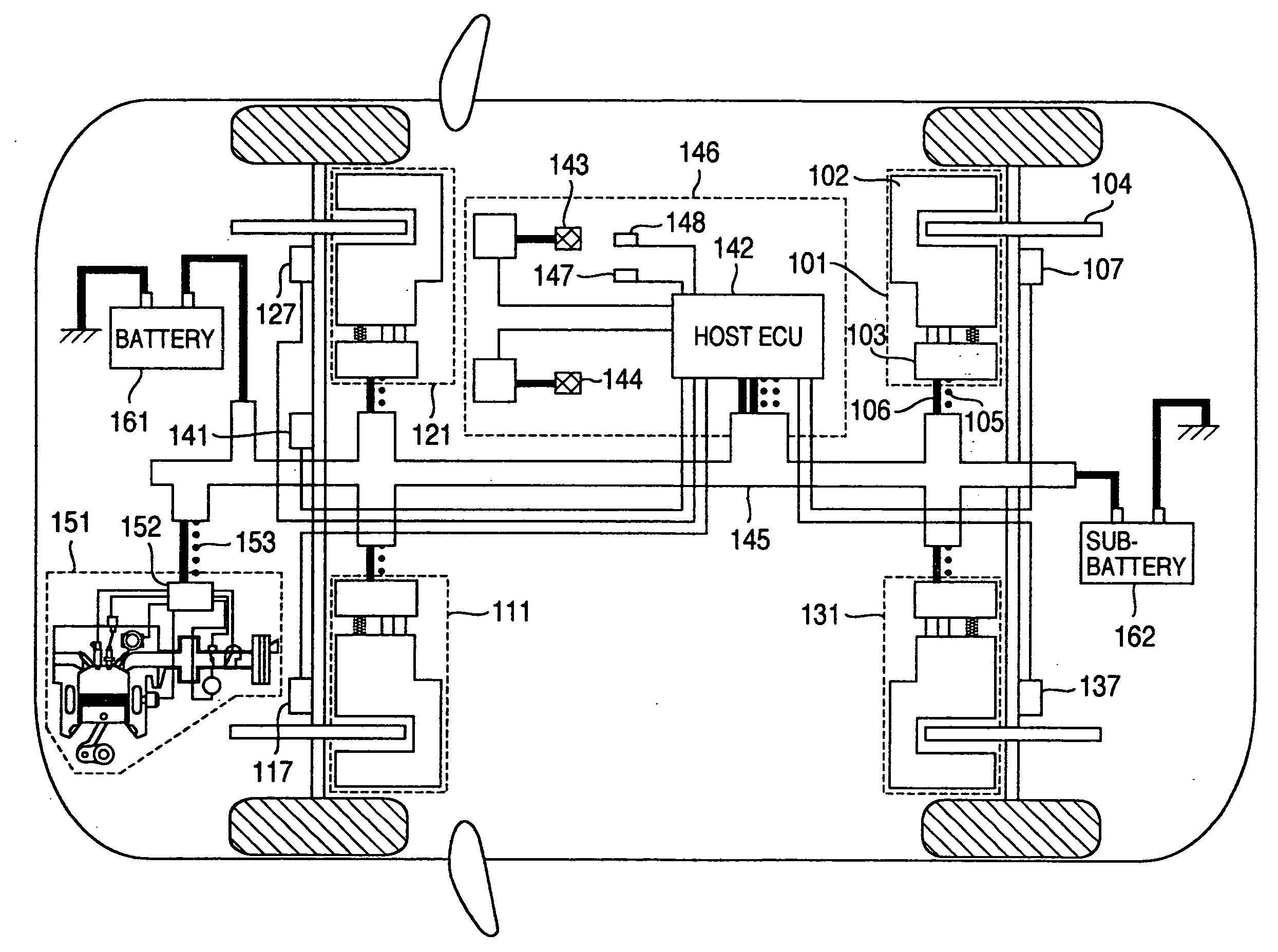
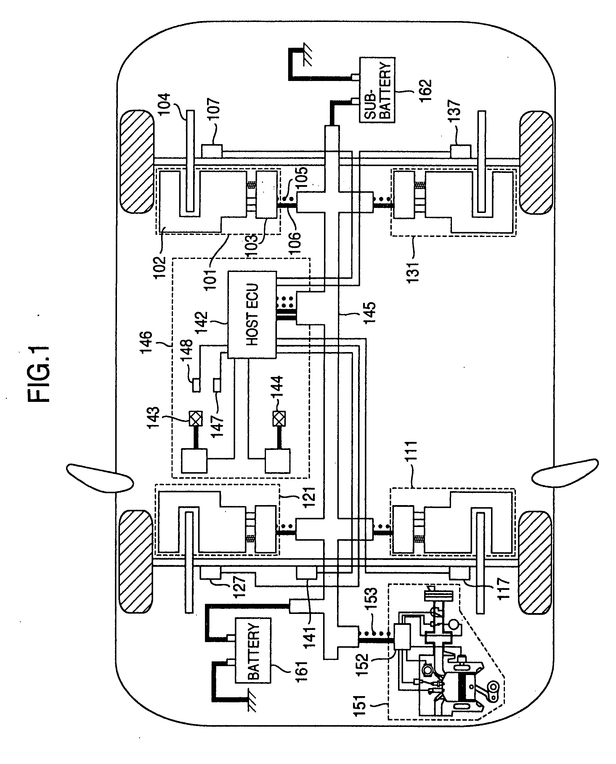
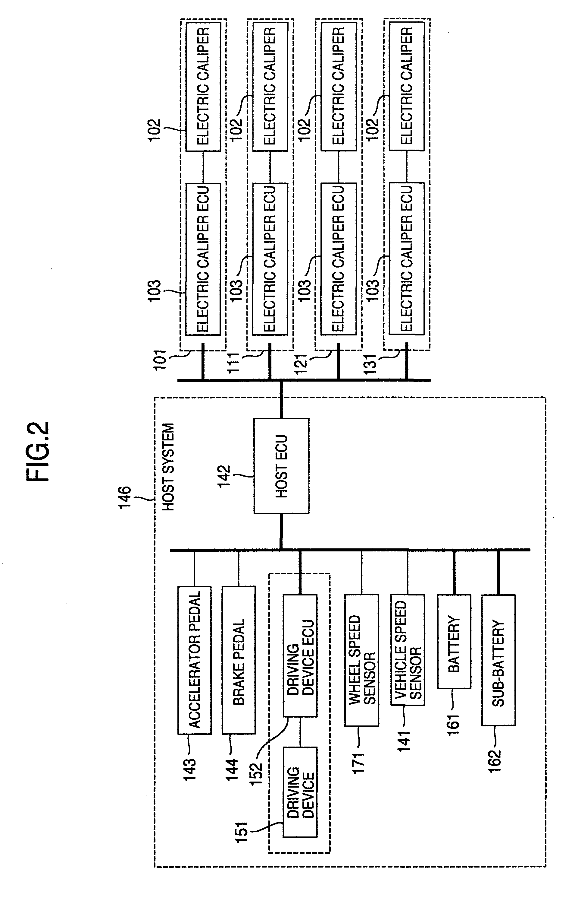
[0037]FIG. 1 shows a system constitution diagram of a vehicle according to one embodiment of the present invention. FIG. 2 shows a system block diagram of FIG. 1.

[0038]Reference numeral 101 is an electric braking apparatus which generates a braking force in the vehicle. The electric braking apparatus includes an electric caliper 102 and an electric caliper ECU 103. The electric caliper presses a piston onto a rotor 104 by an electric actuator or motor to generate the braking force in the vehicle. The electric caliper ECU 103 receives power supply from a power route 106 connected to a main battery 161 or a sub-battery 162, and controls a current and a voltage so as to drive the motor of the electric caliper 102. The electric caliper ECU 103 controls the electric caliper 102 based on information of the electric caliper 102 and an instruction...


PUM


Abstract

An electric braking apparatus which first moves a piston in a detaching direction or passes a current to move the piston in the detaching direction in order to detect a pad contacting position. Furthermore, while the piston moves in the detaching direction, pad non-contact judgment is performed. After a pad non-contact state is confirmed, the piston is moved in a pressing direction to detect the pad contacting position. When the piston does not move in the detaching direction, it is judged that a parking brake has an ON-state, and it is waited until a host system instructs parking brake release.

Description

CROSS-REFERENCE TO RELATED APPLICATION[0001]The present application relates to subject matters described in a co-pending patent application Ser. No. ______ to be filed on Aug. 10, 2007 entitled “ELECTRIC BRAKING APPARATUS AND METHOD OF CONTROLLING THEREOF” by Yasufumi Konishi, et al. and assigned to the assignees of the present application. The disclosures of this co-pending application are incorporated herein by reference.BACKGROUND OF THE INVENTION[0002]The present invention relates to an electric braking apparatus which generates a braking force in a vehicle by a motor, and a vehicle on which the apparatus is mounted.[0003]Heretofore, braking of a vehicle has been realized by multiplying a depressing force exerted on a pedal by a driver and transmitting the force to a hydraulic caliper of wheels by a hydraulic system. However, in recent years, owing to development of an electronic technology, a “by-wire” system is developed in which an amount of the pedal to be depressed is acqui...

Claims


Application Information

Patent Timeline
IPC IPC(8): F16D65/16B60T13/74F16D65/18
CPCB60T1/10B60T13/741B60T13/746F16D2121/24F16D2066/003F16D2066/005F16D2066/006F16D65/18
Inventor UENO, KENTAROUSASAKI, MITSUHIDEOIKAWA, HIROTAKAYAMAGUCHI, TOHMATAKEDA, HIROKI
Owner HITACHI ASTEMO LTD
Why Eureka
Try Eureka