Starter-generator operable with multiple variable frequencies and voltages

a starter generator and variable frequency technology, applied in the direction of engine starters, synchronous motors, electric generator control, etc., can solve the problems of increasing the overall complexity, cost and maintenance, and the overall complexity of the electronic circuit relative to the heavy power

Active Publication Date: 2008-03-20
HONEYWELL INT INC
View PDF14 Cites 26 Cited by
  • Summary
  • Abstract
  • Description
  • Claims
  • Application Information

AI Technical Summary

Benefits of technology

The present invention is a system that can provide electrical power at different frequencies and voltages to a gas turbine engine to help it start. This system can also produce controllable torque to the engine.

Problems solved by technology

The technical problem addressed in this patent is the need for a generator that can supply various loads without requiring complex and heavy inverters and frequency control circuits, while also avoiding the drawbacks of brush-type DC machines such as reduced reliability, frequent maintenance and cleaning, and torque ripple during startup.

Method used


Image

  • Starter-generator operable with multiple variable frequencies and voltages
  • Starter-generator operable with multiple variable frequencies and voltages
  • Starter-generator operable with multiple variable frequencies and voltages

Examples


Embodiment Construction

[0020]The following detailed description of the invention is merely exemplary in nature and is not intended to limit the invention or the application and uses of the invention. Furthermore, there is no intention to be bound by any theory presented in the preceding background or the following detailed description. In this regard, although the starter-generator is described herein as being used with, for example, an aircraft gas turbine engine, it will be appreciated that may it be used as a starter-generator with gas turbine engines in numerous other environments including, for example, space, marine, land, or other vehicle-related applications where gas turbine engines are used.

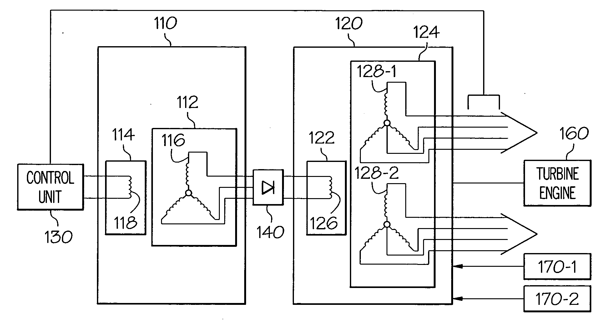
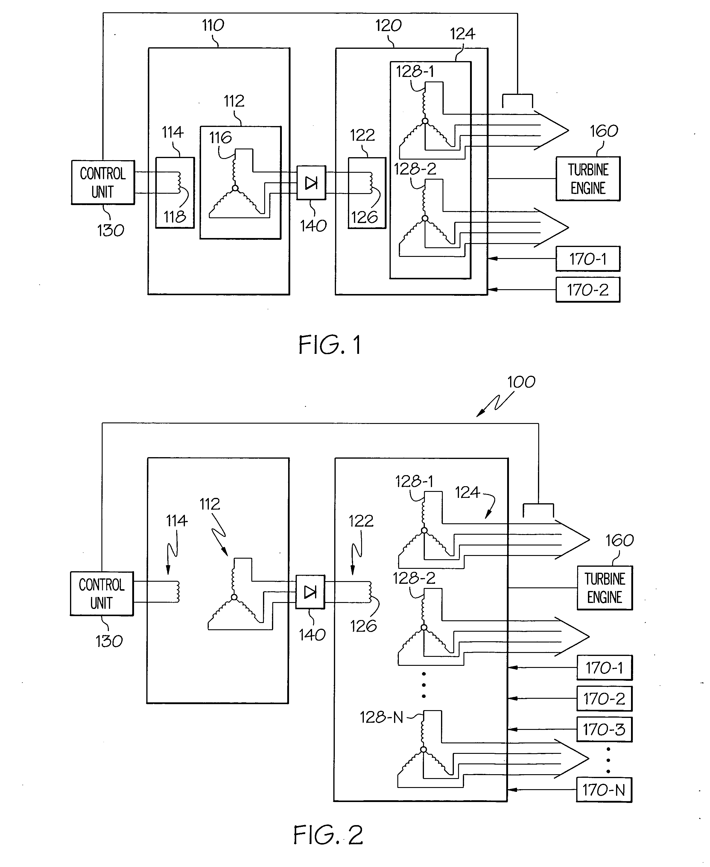
[0021]Turning now to FIG. 1, a functional schematic diagram of an exemplary starter-generator system 100 for use with, for example, an aircraft gas turbine engine, is depicted. This exemplary starter-generator system 100 includes an exciter 110, which includes an exciter rotor 112 and an exciter stator 114, a...


PUM


Abstract

A starter-generator system is configured to be operable at multiple variable frequencies. The starter-generator includes a rotor and a stator. The rotor is configured to rotate and has a single main field winding wound thereon. The stator has at least a first stator winding set and second stator winding set independently wound thereon. Upon electrical excitation and rotation of the rotor the starter-generator supplies electrical power from each of the stator winding sets at different frequencies. Also, upon electrically exciting one or both of the stator winding sets with appropriate AC power, the rotor will rotate and generate a starting torque.

Description


Claims


Application Information

Patent Timeline
Owner HONEYWELL INT INC
Why Eureka
Try Eureka