
Electric starter generator system employing bidirectional buck-boost power converters, and methods therefor

a power converter and electric starter technology, which is applied in the direction of electric controllers, dynamo-electric converter control, instruments, etc., can solve the problems of large capacitor banks, unacceptably large dc voltages supplied from rectifiers to loads, and high ac impedances,

Active Publication Date: 2008-02-05
GENERAL ELECTRIC CO
View PDF32 Cites 44 Cited by
  • Summary
  • Abstract
  • Description
  • Claims
  • Application Information

AI Technical Summary

Problems solved by technology

However, when the loads are suddenly applied or removed, the high AC impedances are a problem.
This is the case, because the changes in the DC voltages supplied from the rectifier to the loads, as a result of the application or removal of the loads, are unacceptably large.
However, the large capacitor bank adds much size and weight, which is problematic in a system in which size and weight must be limited as much as possible.

Method used


Image

  • Electric starter generator system employing bidirectional buck-boost power converters, and methods therefor
  • Electric starter generator system employing bidirectional buck-boost power converters, and methods therefor
  • Electric starter generator system employing bidirectional buck-boost power converters, and methods therefor

Examples


Embodiment Construction

[0011]The present invention will be explained in further detail by making reference to the accompanying drawings, which do not limit the scope of the invention in any way.

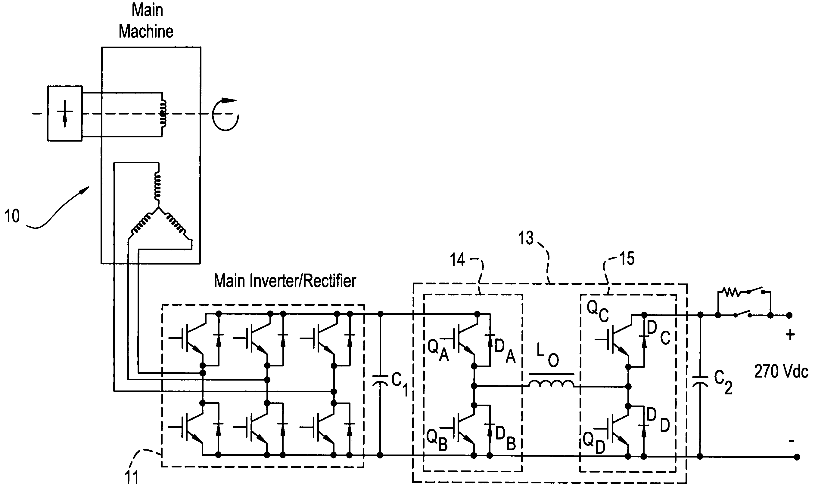
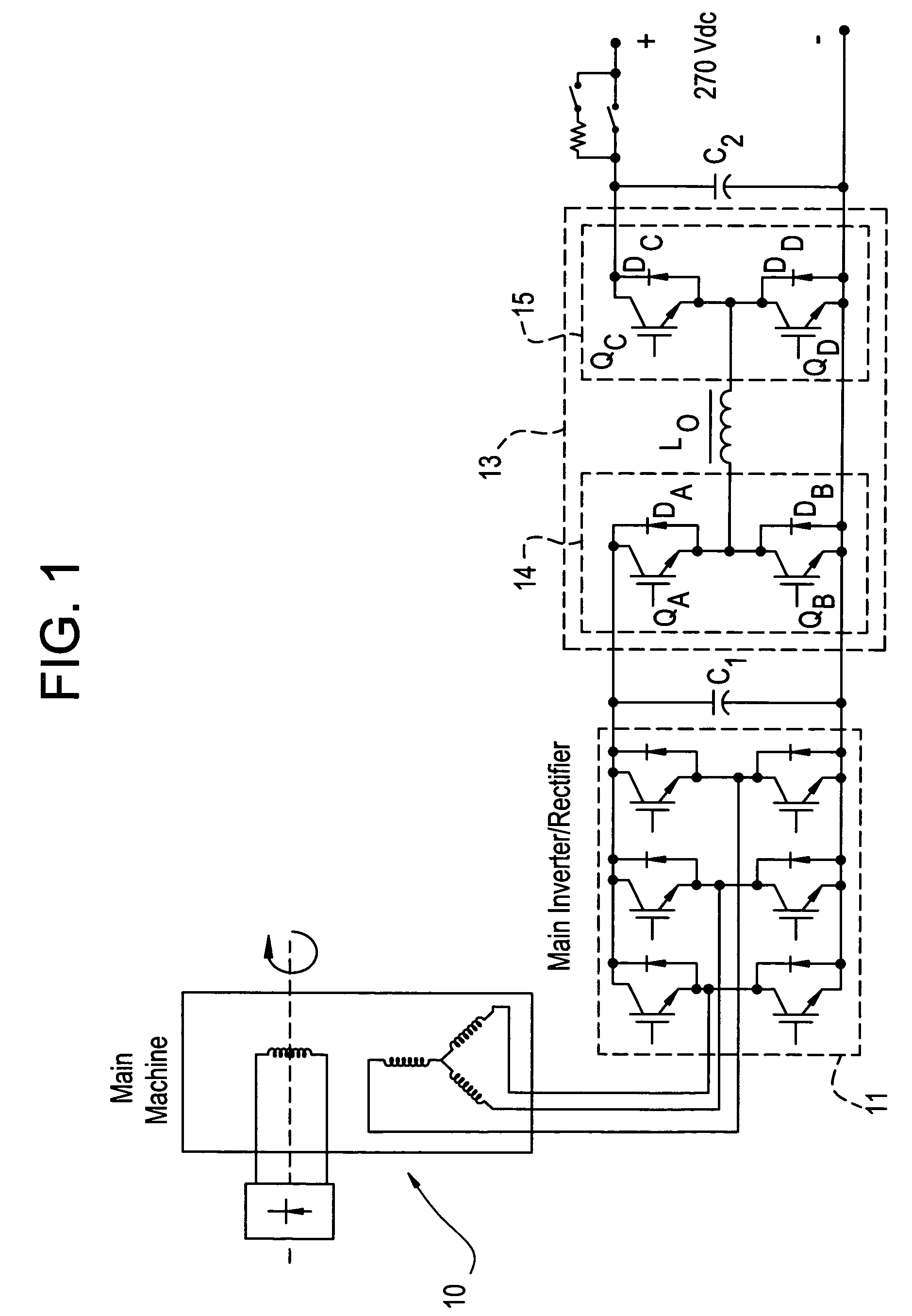
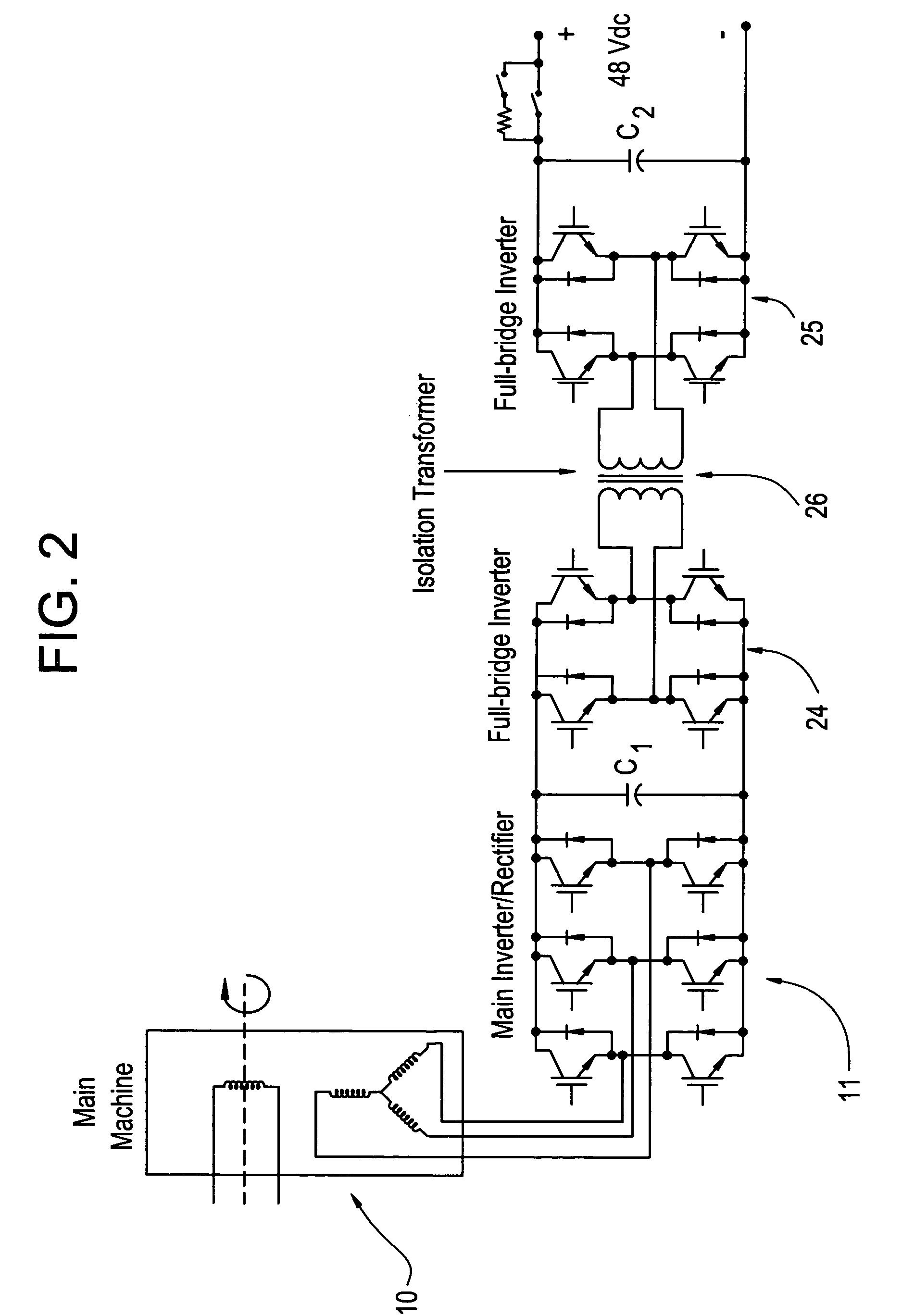
[0012]In an embodiment of the invention, two bi-directional buck-boost converters are configured at the output of an AC machine / inverter / rectifier system to allow controlled power flow in either direction, for starting or generating, while enabling fast transient response for sudden load changes. Since the voltage can be bucked or boosted in either direction, the output voltage can be maintained during a sudden load application or load removal, through control of the buck-boost converters.

[0013]A bidirectional buck-boost power converter embodiment is described with reference to FIG. 1. Although adaptable to both DC and AC machines, the exemplary bidirectional buck-boost power converter circuit 13 discussed with reference to FIG. 1 is configured for an AC machine. FIG. 1 illustrates an AC machine 10 having a 3-phase...


PUM


Abstract

A bidirectional buck-boost power converter 13 including a pair of inverter modules 14, 15 disposed at an output of a machine, and an inductor Lo connected between the pair of inverter modules 14, 15. A method for controlling a voltage output of a machine starter generator having an inverter rectifier and bidirectional buck-boost converter, includes outputting a dc voltage controlled by bidirectional buck-boost pulse width modulation (PWM) switching control, when the starter generator is in a generator mode.

Description

BACKGROUND OF THE INVENTION[0001]This invention relates to controlling the output of AC machines, and more particularly, to a buck-boost power converter for controlling the output of an electric starter generator.[0002]High speed AC machines optimized for small size can have high AC impedances. During steady state operation when generating power to a DC load through a rectifier, the high AC impedances are not a major problem. However, when the loads are suddenly applied or removed, the high AC impedances are a problem. This is the case, because the changes in the DC voltages supplied from the rectifier to the loads, as a result of the application or removal of the loads, are unacceptably large.[0003]One manner in which this problem has been addressed is to use a large capacitor bank at the output of the rectifier to supply or absorb the transient energy. However, the large capacitor bank adds much size and weight, which is problematic in a system in which size and weight must be lim...

Claims


Application Information

Patent Timeline
Patent Type & Authority Patents(United States)
IPC IPC(8): G05B11/28
CPCH02M3/1582
Inventor STEIGERWALD, ROBERT LOUISGARCES, LUIS JOSEBRINGMAN, MATTHEW CHRISTOPHER
Owner GENERAL ELECTRIC CO
Learn More