Rocking Chair and Anti-Skid Base

a technology of rocking chair and base, which is applied in the field of rocking chairs, can solve the problems of user discomfort, inability to comfortably rock for very long, and the rocking chair is typically susceptible to longitudinal and rotational movement, and achieves the effect of preventing substantial movement of the rocking chair

Inactive Publication Date: 2008-03-27
CHURCH OF SPIRITUAL TECH
View PDF18 Cites 9 Cited by
  • Summary
  • Abstract
  • Description
  • Claims
  • Application Information

AI Technical Summary

Benefits of technology

[0004]The invention herein is directed to preventing substantial movement of the rocking chair during the rocking motion. In accordance with the invention, a rocking chair is utilized having a pair of transversely-spaced, generally longitudinally extending rockers that converge at a first angle. A base is provided having a pair of transversely-spaced generally longitudinally extending channels that converge at a second angle at least approximately the same as the first angle. The channels are positioned to underlie the rockers as the rocking chair is rocked. The transverse width of each channel is sufficiently wider than the transverse width of the respective rocker to accommodate the rocker within the channel during rocking motion of the chair, and is sufficiently narrower than the transverse width of the respective rocker to prevent substantial longitudinal movement of the rockers within the channels.

Problems solved by technology

Rocking chairs are typically susceptible to longitudinal and rotational movement during use.
The movement is most noticeable, and annoying, when the user's feet are placed on a foot stool or other elevated object for comfort, and the chair is found to move toward and / or away from the object and / or to rotate away from that object after a few oscillations.
The result is that the user cannot comfortably rock for very long without repeatedly adjusting the chair's position or electing to forego the comfort of elevated feet.
Thirdly, it appears that the nap of the carpet applies a force against the rockers of the chair that tends to produce a displacing movement of the chair during the rocking movement, typically laterally.

Method used


Image

  • Rocking Chair and Anti-Skid Base
  • Rocking Chair and Anti-Skid Base
  • Rocking Chair and Anti-Skid Base

Examples


Embodiment Construction

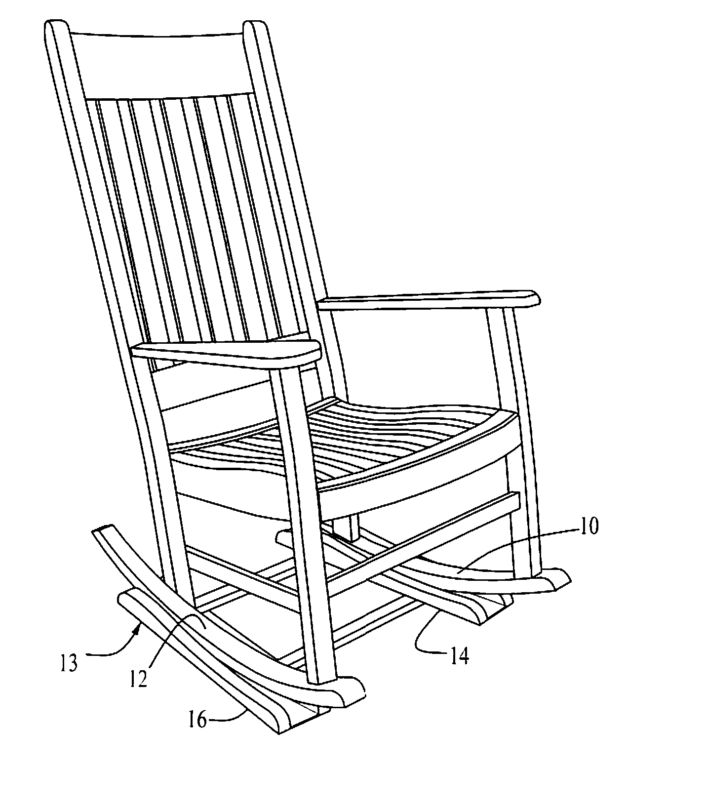
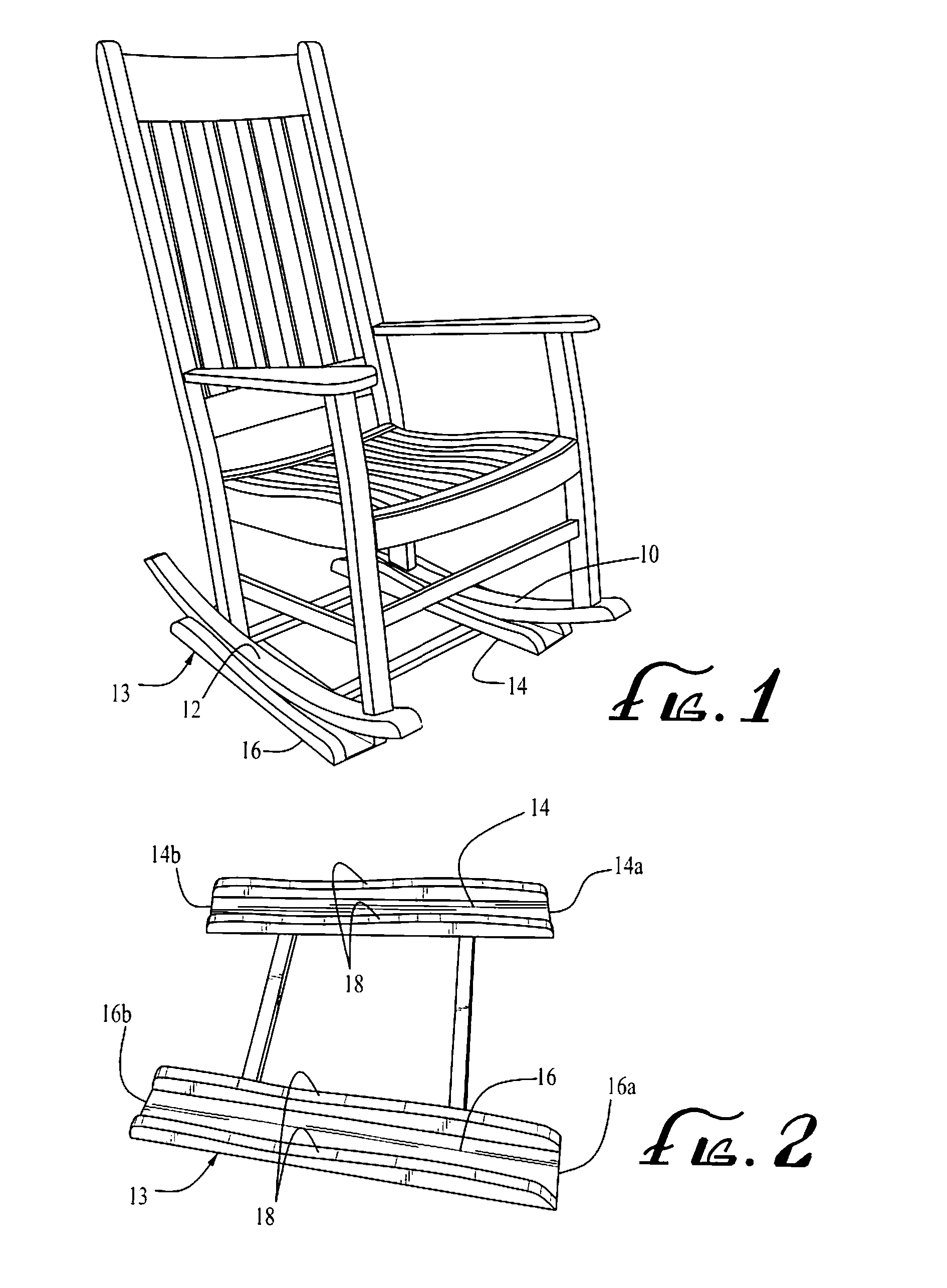
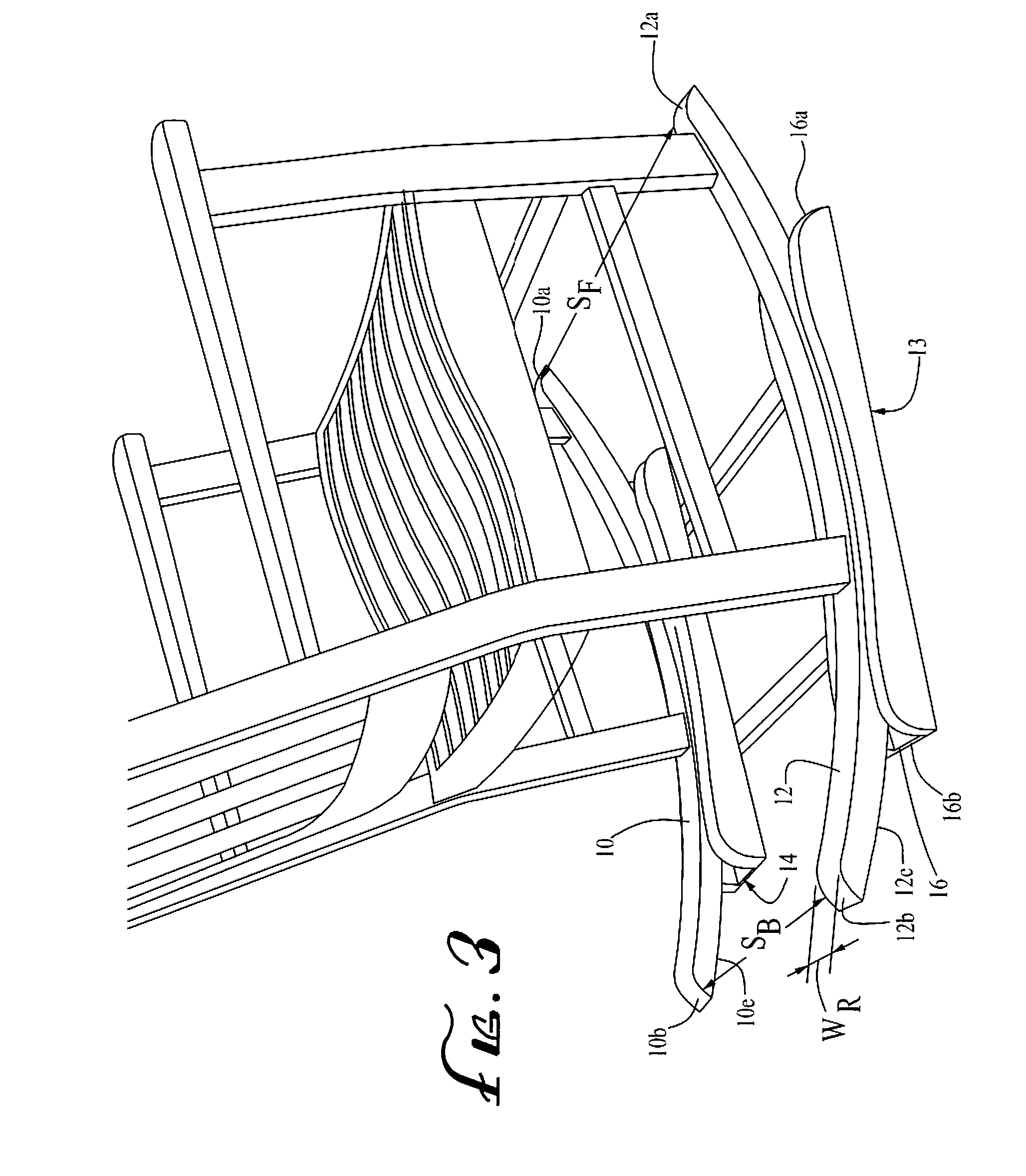
[0013]FIG. 1 is a perspective view of a rocking chair and non-skid base constricted in accordance with the invention. FIG. 3 is a side perspective view of the rocking chair and base of FIG. 1. As illustrated in these Figures, the rocking chair has a pair of transversely-spaced, generally longitudinally extending rockers 10, 12 that each extend from a front end 10a, 12a to a rear end 10b, 12b, with an arced bottom surface 10e, 12e that supports the chair for rocking movement in the conventional manner.

[0014]As best illustrated in FIG. 5, the rockers 10, 12 converge at a first angle θ1 towards the rear of the chair. Each rocker of the preferred embodiment forms an angle of approximately 5° with the longitudinal axis 18 passing centrally between the rockers, wherein the term “longitudinal” is used to denote the direction in which the rocking chair faces, and the axis extends centrally between the rockers. Accordingly, the rockers mutually converge at an angle θ1 of approximately 10°. I...


PUM


Abstract

Longitudinal and rotational movement of a rocking chair during the rocking motion is substantially prevented with a rocking chair having a pair of transversely-spaced, generally longitudinally extending rockers that converge at a first angle. A base is provided having a pair of transversely-spaced, generally longitudinally extending channels that converge at a second angle at least approximately the same as the first angle. The channels are positioned to underlie the rockers as the rocking chair is rocked. The transverse width of each channel is sufficiently wider than the transverse width of the respective rocker to accommodate the rocker within the channel during rocking motion of the chair, and is sufficiently narrower than the transverse width of the respective rocker to prevent substantial longitudinal movement of the rockers within the channels.

Description

FIELD OF THE INVENTION[0001]This invention relates to rocking chairs and, more particularly, to rocking chairs having rockers which contact channels or tracks in a base.BACKGROUND OF THE INVENTION[0002]Rocking chairs are typically susceptible to longitudinal and rotational movement during use. (As used herein, the term “longitudinal” will be used to mean the direction in which the chair is facing and, hence, the direction in which rocking takes place.) The movement is most noticeable, and annoying, when the user's feet are placed on a foot stool or other elevated object for comfort, and the chair is found to move toward and / or away from the object and / or to rotate away from that object after a few oscillations. This is particularly true on rugs and carpeting but also happens on non-carpeted surfaces, particularly such as hardwood floors. The result is that the user cannot comfortably rock for very long without repeatedly adjusting the chair's position or electing to forego the comfo...

Claims


Application Information

Patent Timeline
Patent Type & Authority Applications(United States)
IPC IPC(8): A47C3/027
CPCA47C3/027
Inventor BELLIN, RUSSELL D.
Owner CHURCH OF SPIRITUAL TECH
Why Eureka
Try Eureka