Percussion instrument systems and methods

a technology of percussion instruments and systems, applied in the field of percussion instruments, can solve problems such as increasing the weight of drums, and achieve the effect of convenient positioning

Active Publication Date: 2010-12-16
ROLAND CORP
View PDF5 Cites 6 Cited by
  • Summary
  • Abstract
  • Description
  • Claims
  • Application Information

AI Technical Summary

Benefits of technology

[0011]In such embodiments, the tensile force on the plurality of fixing devices arranged on the shell may be dispersed, and the head can be stretched. Thus, the fixing devices can be attached to the shell without using a strong, rigid ring like in the prior art, which may not break or otherwise become deformed, and may increase the weight of the drum. Thus, in addition, omission of the ring may reduce a weight of the drum.
[0014]In such embodiments, the wall of the fixing device may not be visible from the outer peripheral surface of the shell, which may provide a better appearance of the shell. In addition, because the wall of the fixing device and the base of the fixing device are arranged adjacent the inner peripheral surface of the shell and the second end of the shell, respectively, and only the extension of the fixing device extends beyond the outer periphery of the shell, a bending force on the extension of the fixing device may not bend the extension of the fixing device easily. Thus, a smaller and / or lighter fixing device than previously used may be employed while still providing similar holding and / or coupling characteristics with the coupling device. As such, a weight of the fixing device, and thus the drum may be reduced.
[0016]In such embodiments, the fixing device may include a locking arm formed on the wall of the fixing device, and the shell may include a locking aperture aligned with the locking arm into which the locking arm may be fit. Accordingly, the fixing device can be positioned easily when the wall of the fixing device is attached to or otherwise arranged on the shell.
[0017]In addition, because the base of the fixing device may be arranged on the second end of the shell, the fixing device may be constrained at the base and at the locking arm, which may prevent substantial movement of the fixing device when the fastener is inserted into the insertion hole and the attaching hole to attach the fixing device to the shell.
[0019]In such embodiments, in a case where the rod member is adjusted, for example, to stretch the head, the space may allow the insertion member and the threaded rod to retain a common axis while an angle of the extension of the fixing device relative to the insertion portion changes from the force of the coupling device acting upon it. That is, the insertion portion may be allowed to move along the attachment hole of the fixing device while retaining a common axis with the threaded rod as the threaded rod is adjusted. Such embodiments, for example, may reduce a force acting on the threaded rod in a direction perpendicular to the axis of the threaded rod. Accordingly, excessive force may not be required to attach and detach the threaded rod, thus simplifying the attachment and removal process. In addition, such embodiments may reduce damage to threads on the threaded rod and / or improve durability of the coupling device.
[0021]Accordingly, vibration of the fixing device fixed to the second end of the shell may be reduced, which may substantially prevent a change in a timbre of the drum. In particular embodiments, the cover may suppress vibration of the fixing device, which may reduce vibration transmitted to the coupling device.

Problems solved by technology

Thus, the fixing devices can be attached to the shell without using a strong, rigid ring like in the prior art, which may not break or otherwise become deformed, and may increase the weight of the drum.

Method used


Image

  • Percussion instrument systems and methods
  • Percussion instrument systems and methods
  • Percussion instrument systems and methods

Examples


Embodiment Construction

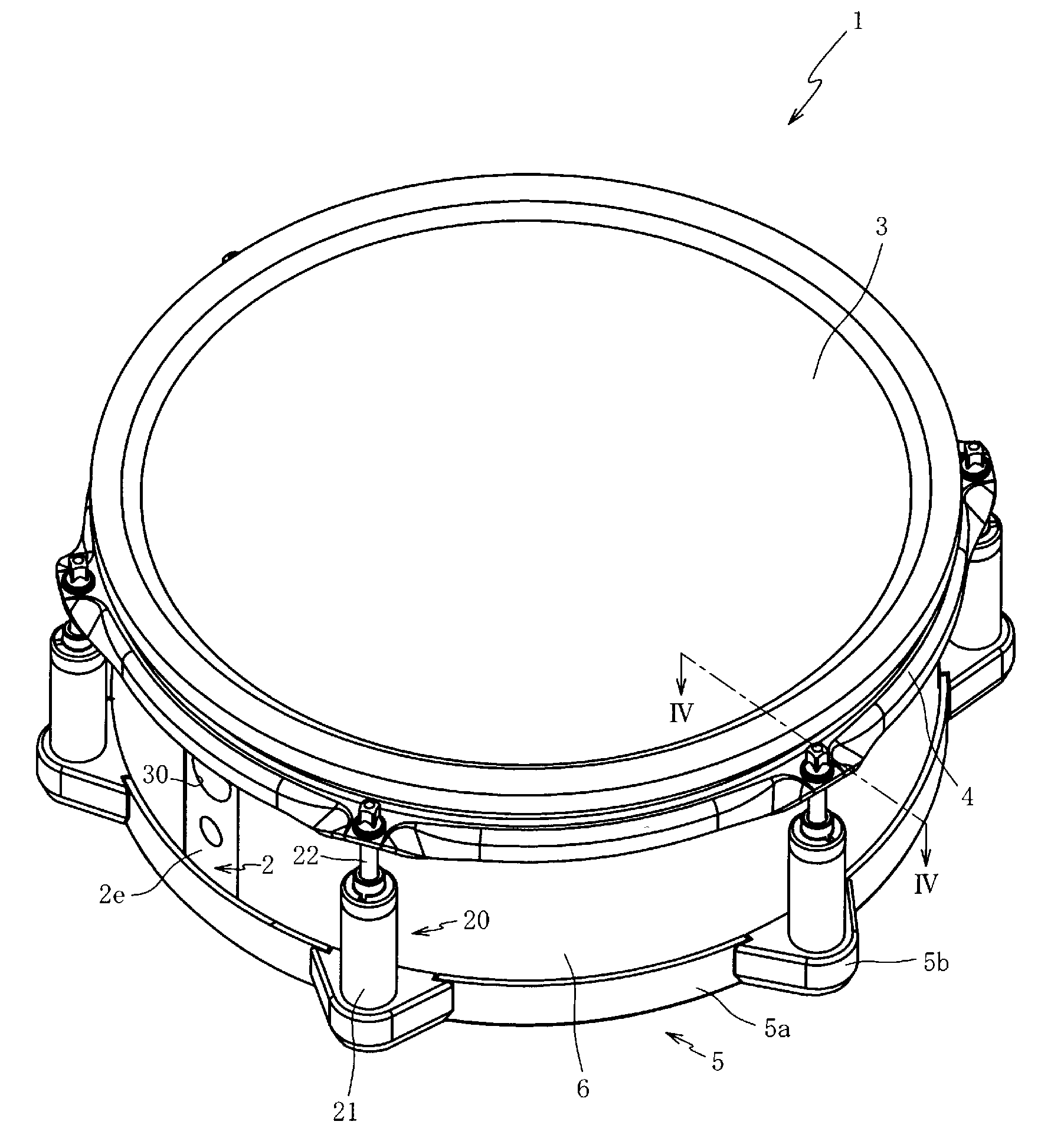
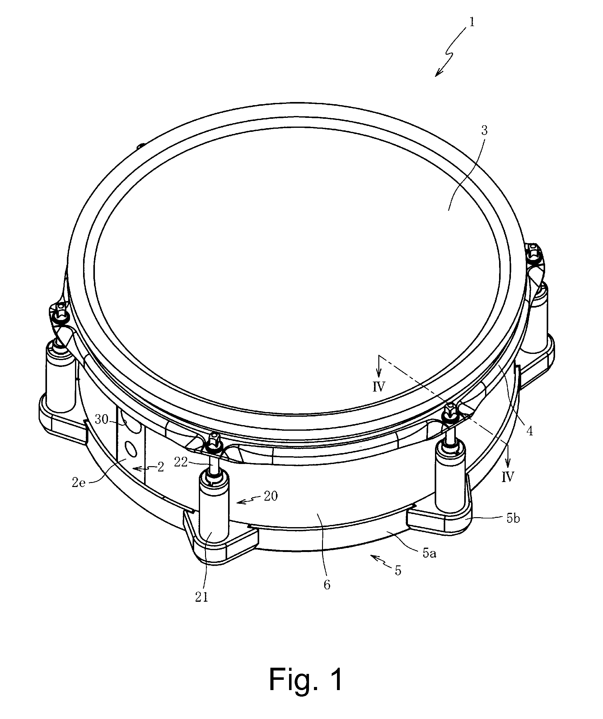
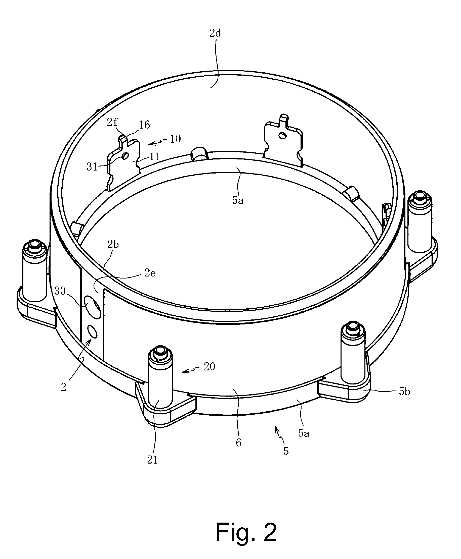
[0043]FIG. 1 is a perspective view drawing of a percussion instrument according to an embodiment of the present invention. The percussion instrument may be a drum 1, or the like. The drum 1 may comprise a shell (or body) 2, a head (or membrane) 3, a hoop member 4, a plurality of fixing devices (or fixtures) 10 (e.g., FIG. 2), and a plurality of coupling devices (or adjustment devices) 20. Reference may be made to an individual fixing device 10 and / or an individual coupling device 20 as applying to all other fixing devices of the plurality of fixing devices 10 and / or all other coupling devices of the plurality of coupling devices 20, respectively, unless otherwise noted.

[0044]The head 3 may be stretched across a first end 2b (e.g., FIG. 2) of the shell 2 to provide a striking surface. In some embodiments, the head 3 may be made of (but not limited to) a flexible material, such as a soft synthetic resin, an elastomer, rubber, and / or the like. In other embodiments, the head 3 may be ma...


PUM


Abstract

A percussion instrument may have a hoop member configured to hold down a head stretched across a first end of the shell by a plurality of adjustment devices that may be for operatively connecting the hoop member with a plurality of fixtures that may be arrangeable along at least two surfaces of the shell.

Description

CROSS-REFERENCE TO RELATED PATENT APPLICATIONS[0001]Japan Priority Application 2009-139243, filed Jun. 10, 2009 including the specification, drawings, claims and abstract, is incorporated herein by reference in its entirety.BACKGROUND[0002]1. Field of the Invention[0003]Embodiments of the present invention generally relate to percussion instruments, and, in specific embodiments, to drums having improved weight properties.[0004]2. Related Art[0005]Typically, a drum includes a shell (or body) with a head (or membrane) placed over one or more ends of the shell. An outer peripheral edge of the head is held against the shell with a hoop. The hoop is clamped to the shell with bolts or the like along the axial direction of the shell. Accordingly, the head is stretched and a specified tensile force can be applied to the head.[0006]Other drums include additional hardware (e.g., lugs) attached to an outer peripheral edge of the shell to allow the hoop member to be clamped accordingly. However...

Claims


Application Information

Patent Timeline
Patent Type & Authority Applications(United States)
IPC IPC(8): G10D13/02
CPCG10D13/023G10D13/16G10D13/02
Inventor YOSHINO, KIYOSHIHIGUCHI, HIDEKAZU
Owner ROLAND CORP
Why Eureka
Try Eureka