
End cap for a corrugated hurricane shutter within an H-header

a hurricane shutter and end cap technology, applied in hurricane shutters, shutters/movable grilles, construction fastening devices, etc., can solve the problems of other limitations of related art, structure to fail building code testing, etc., and achieve the effect of preventing substantial movemen

Inactive Publication Date: 2009-10-29
MOTOSKO STEPHEN J +1
View PDF18 Cites 6 Cited by
  • Summary
  • Abstract
  • Description
  • Claims
  • Application Information

AI Technical Summary

Benefits of technology

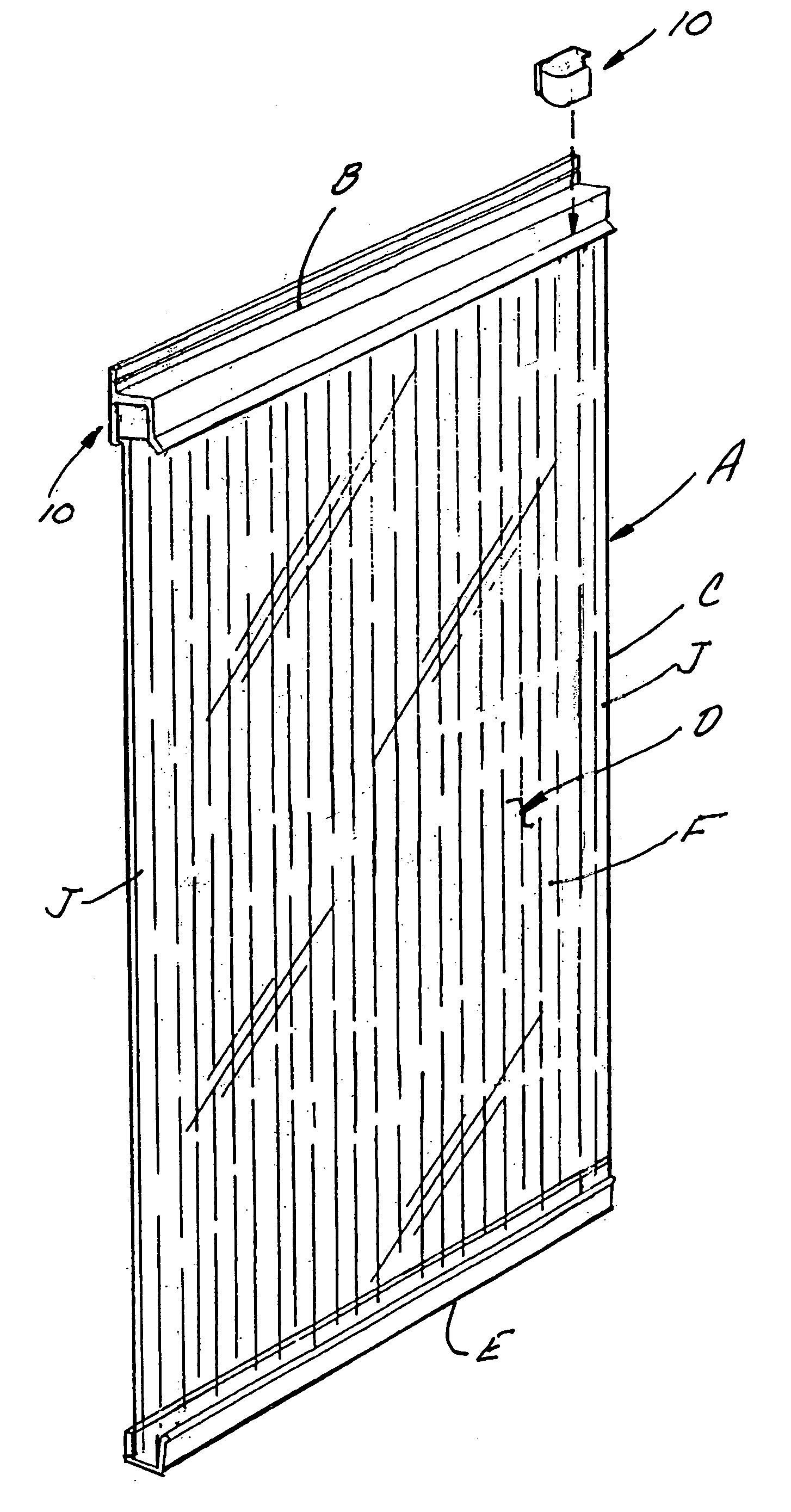
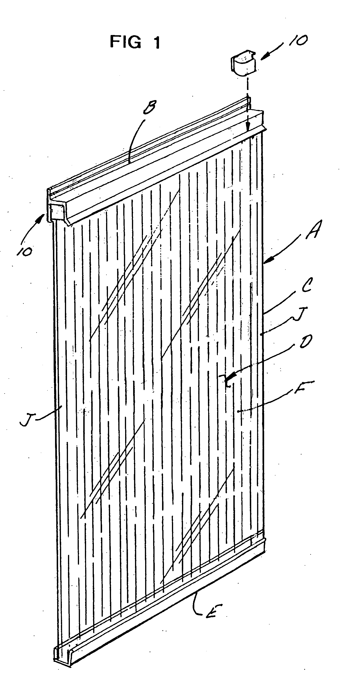
[0012]This invention is directed to an end cap for an H-shaped header bar used to secure a corrugated polycarbonate hurricane shutter attachable to a window frame. The H-header has a generally inverted U-shaped pocket adapted in size to receive an upper margin of the hurricane shutter, with the end cap positioned in each end of the header bar. The H-header cooperates with a lower support channel also attached to the window frame to support and secure the hurricane shutter over the window. The end cap is dependently positionable within an inner upright side of the pocket to engage with the upper corner of the hurricane shutter, strengthening and preventing substantial movement from flying object impact during heavy hurricane wind conditions and building code testing therefor.
[0013]It is therefore an object of this invention to provide an end cap securable around each upper corner of a polycarbonate corrugated hurricane shutter and dependently positionable within the ends of the header to strengthen and prevent unacceptable upper corner deformation and expansion movement of the hurricane shutter during hurricane and tropical storm conditions.
[0014]It is therefore an object of this invention to provide an end cap securable around each upper corner of a polycarbonate corrugated hurricane shutter and dependently positionable within the ends of the header to strengthen and prevent unacceptable upper corner deformation and expansion movement of the hurricane shutter during hurricane and tropical storm conditions during building code testing procedures.

Problems solved by technology

It has been shown that, although the polycarbonate corrugated hurricane shutter structure is generally adequate to withstand such impact, when incorporated into conventional H-headers for support, impact in the vicinity of the upper portions of the hurricane shutter results in excessive deformation of the corrugations and expansion of those corrugations, causing the structure to fail building code testing.
Other limitations of the related art will become apparent to those skilled in the art upon a reading of the specification and a study of the drawings.

Method used


Image

  • End cap for a corrugated hurricane shutter within an H-header
  • End cap for a corrugated hurricane shutter within an H-header
  • End cap for a corrugated hurricane shutter within an H-header

Examples


second embodiment

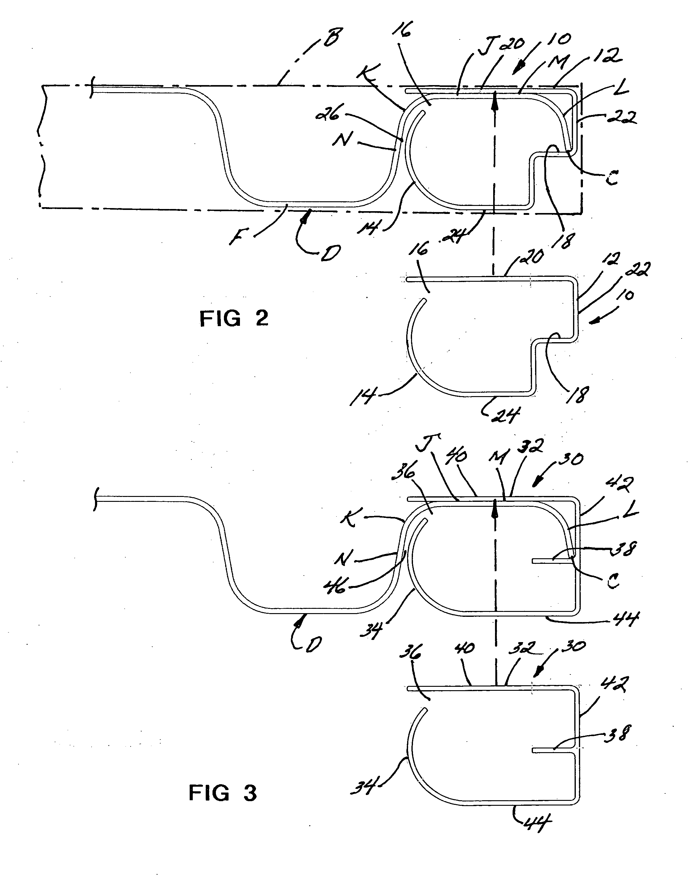
[0038]Referring now to FIG. 3, the invention is there shown wherein the front upright surface 44 extends across a more substantial length of the housing 32 while still maintaining an end stop 38 for supportingly bearing against the upright edge C of the hurricane shutter D. As previously described, the flat M of the first corrugation J bears against the rear upright wall 40 while the first neutral portion N is closely spaced at 46 with respect to the arcuate inner side wall 34. The outer side wall 42, in combination with stop surface 38, entraps the edge C of the hurricane shutter D.

third embodiment

[0039]Referring now to FIGS. 4 to 7, the invention is there shown generally at numeral 50 and also includes a molded or extruded plastic or metal housing 52 having an arcuate inner side wall 54 which in combination with the upright back panel 60 forms the access slot 56 which functions as previously described. The combination of the stop surface 58 and the outer side wall 62 define an entrapment means similar to that previously described. The front upright surface 64 is again elongated similar to that shown in FIG. 3.

fourth embodiment

[0040]Referring now to FIGS. 8 to 12, the invention is there shown generally at numeral 70 and also includes a molded plastic or metal housing 72 having an inner arcuate surface 74 blending uniformly from the front upright surface 84. The back upright surface 80 defines, in combination with the end of the inner side wall 74, the access slot 76. The front upright wall 84 is of a length similar to that in FIG. 3, while the combination of outer upright side wall 82 and stop surface 78 define the entrapment means for the edge C of the upper corner of the hurricane shutter D as previously described. In this embodiment of the housing 72, a solid top surface 86 is also provided as an end stop for the upper end corner of the first corrugation J of the hurricane shutter D for added stability.

[0041]FIGS. 8A and 12A show an alternate embodiment of the invention shown at numeral 70 in FIGS. 8 and 12. This embodiment 70′ includes all of the features previously described in FIGS. 8 and 12 with re...


PUM


Abstract

An end cap for an H-shaped header bar used to secure a corrugated hurricane shutter attachable to a window frame and having a generally inverted U-shaped pocket adapted in size to receive an upper margin of the hurricane shutter and the end cap at each end of the header bar. The header bar cooperates with a lower support channel also attached to the window frame to support and secure the hurricane shutter over the window. An end cap is positionable and attachable within an inner upright side of the pocket to engage with the upper corner of the hurricane shutter preventing substantial lateral expansion movement or corrugation deformation from being struck by flying objects during heavy hurricane wind.

Description

CROSS-REFERENCE TO RELATED APPLICATIONS[0001]Not applicableSTATEMENT REGARDING FEDERALLY SPONSORED RESEARCH OR DEVELOPMENT[0002]Not applicableINCORPORATION-BY-REFERENCE OF MATERIAL SUBMITTED ON A COMPACT DISC[0003]Not applicableBACKGROUND OF THE INVENTION[0004]1. Field of the Invention[0005]This invention relates generally to removable storm and hurricane shutters, and more particularly to an end cap dependently engagable within each end of an upper H-header for supporting the corners of a corrugated hurricane shutter.[0006]2. Description of Related Art[0007]Hurricane shutters have become extremely popular and useful in the hurricane prone sections of the country. Such hurricane shutters are typically deployed prior to an area coming under the influence tropical storm and hurricane weather conditions and serve to prevent damage to the glass windows and portal doors as a result of high winds and flying debris.[0008]An example of such a storm shutter installation is disclosed in U.S. ...

Claims


Application Information

Patent Timeline
Patent Type & Authority Applications(United States)
IPC IPC(8): E06B3/30
CPCE06B2009/005E06B9/02
Inventor MOTOSKO, STEPHEN J.MOTOSKO, III, STEPHEN
Owner MOTOSKO STEPHEN J
Learn More