Rear leg support for easel or the like

a support device and easel technology, applied in the direction of machine supports, furniture parts, lecterns, etc., can solve the problems of rear leg folding, easel instability, and compromise of easel stability

Inactive Publication Date: 2000-10-24
GLEBE GREGORY N
View PDF19 Cites 5 Cited by
  • Summary
  • Abstract
  • Description
  • Claims
  • Application Information

AI Technical Summary

Benefits of technology

In summary, the invention provides a support device for the rear leg of a tripod easel comprising a pair of rearwardly extending relatively rigid support braces each having a first end portion adapted to be pivotally mounted on one of the pair of front legs of the easel. The support braces have second end portions disposed rearwardly of the first end portions and extend angularly towards an apex. At the apex, a rear leg engaging receptacle portion interconnects the two support braces to form a relatively simple and rigid frame. The receptacle portion is configured to receive and fit around the sides and rear surface of the rear leg and is preferably provided with detent means in the form of projections which inwardly extend adjacent the front surface of the leg. Alternative detent means may be utilized such as an elastic O-ring fitted around the braces adjacent the receptacle, a wire clip or an elastomeric band. Preferably, the receptacle portion projects angularly downwardly relative to the plane of the support braces. The receptacle allows for limited movement of the rear leg between the collapsed position and the support position. When in the support position, the rear leg is locked against relative movement with respect to the front legs. In a preferred form, the support device consists of a single, relatively rigid wire form which includes pivotal support projections, the support braces and the receptacle portion including the detent means.
A further objective of the invention is the provision of a stabilizing support for the rear leg of a tripod easel which prevents substantial movement of the rear leg relative to the others in any direction.
A still further objective is the provision of a leg support which immobilizes the rear leg in the folded position to facilitate easy transport.
Other objectives of the invention are the provision of a leg support for a tripod easel which can be manufactured from inexpensive materials which the resulting low cost to the consumer and which is easy to install.

Problems solved by technology

A major draw back of this design is that the rear leg is attached only at the top, and this arrangement allows for a great deal of motion that compromises the stability of the easel.
For example, pushing the easel backwards may cause the rear leg to fold inwardly causing a collapse.
In addition, the weight of the art work or downward pressure may cause the rear leg to slide backwards, also resulting in collapse.
This still leaves the easel unstable with the rear leg vulnerable to lateral movement or, if the easel is pushed, to movement toward the front legs.
It also makes the easel, which is meant to be portable, awkward to move since the rear leg will swing around during transport.
Each of the known alternatives is relatively expensive, and as a result, none of them have been widely adopted.

Method used


Image

  • Rear leg support for easel or the like
  • Rear leg support for easel or the like
  • Rear leg support for easel or the like

Examples


Embodiment Construction

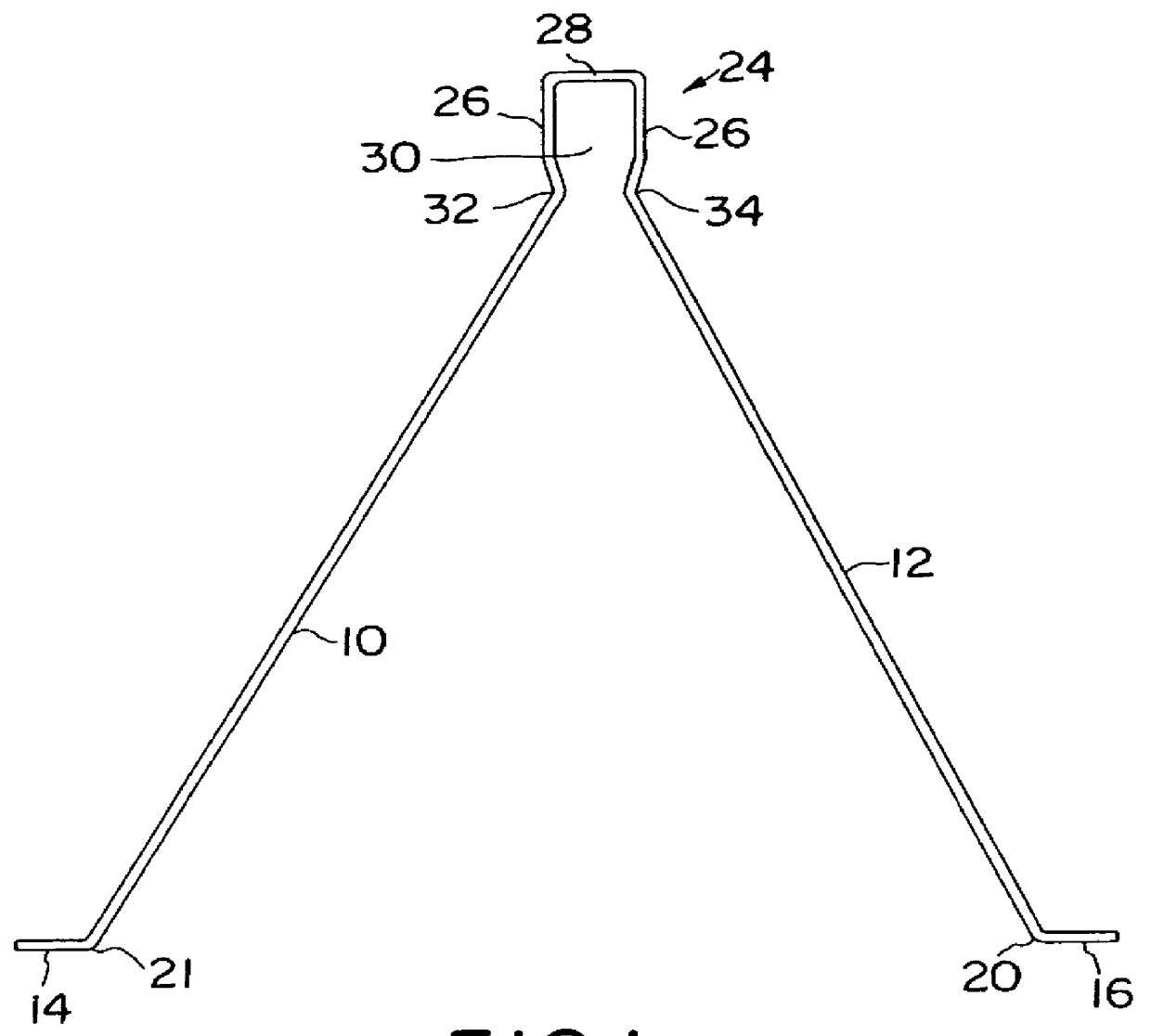
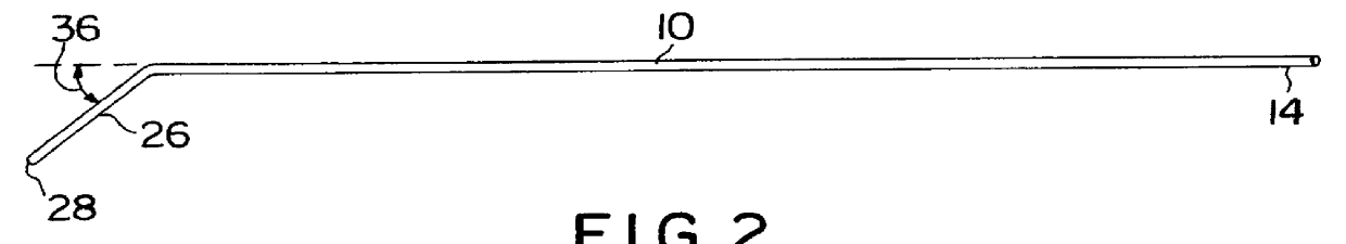
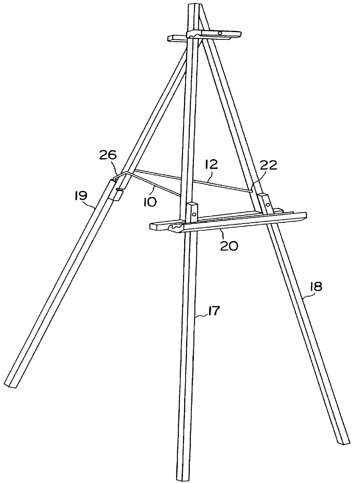
With reference first to FIG. 1, a support device of the presently preferred form of the invention comprises a unitary wire form which consists of substantially straight bracing portions 10 and 12 each having first end portions 14 and 16 which are bent as at 20 and 21 so to project laterally outwardly, thereby forming pivotal supports which fit within recesses in the side portions of the front legs. One such recess 22 is illustrated in the easel of FIG. 3. In FIG. 3, it can be seen that the easel comprises front legs 17 and 18 and a rear leg 19 pivotally mounted to the front legs. A work support 20 is attached to each of the front legs and locks these legs in position with respect to one another. The recesses 22 may be provided for the purpose at the factory or may be drilled into the side edges of the legs by the user of the easel in cases where the user may wish to modify a previously purchased easel.

As can be seen upon further reference to FIG. 1, support brace portions 10 and 12 ...


PUM


Abstract

A tripod easel support device comprising a pair of relatively inwardly inclining bracing elements each joined together at one end at an apex, the apex including a leg-receiving recessed portion conforming to the rear leg profile to receive the rear leg of a tripod easel and further having a pair of inwardly projecting detent surfaces formed to project inwardly of the side surfaces of the rear leg to retain the leg within the recess. The rigid bracing elements are provided with end projections at the ends opposite to the recessed portion for pivotally mounting the device in pre-drilled openings in the side edges of the front legs. The recessed portion slopes downwardly relatively to the bracing elements. When the rear leg is extended, the leg is locked in position between the detent surfaces and the rear wall surface of the recess. For storage, the device is pivoted upwardly and the rear leg moves flush with the front legs. In the upper position of the device, the rear leg is again clamped in position and releasably locked against movement.

Description

This invention relates to easels and like devices, especially tripod easels and stabilizing devices for a rear leg of such easels.Easels of the tripod style have been available for many years for use in displaying works of art, charts, posters and the like, as well as serving as working easels for artists. All such easels are of the same basic design, having legs joined at the top with a rear leg hingedly mounted relative to the others so that it can be shifted between a retracted position adjacent to the plane of the other two legs and an angularly extended position in which the three legs form a triangular support for the art work. In this type of easel, the two front legs are generally joined by a tray which supports the art work while the third leg is relatively movable from the retracted or storage position to the extended position for use.A major draw back of this design is that the rear leg is attached only at the top, and this arrangement allows for a great deal of motion th...

Claims


Application Information

Patent Timeline
Patent Type & Authority Patents(United States)
IPC IPC(8): A47B97/00A47B97/08
CPCA47B97/08
Inventor GLEBE, GREGORY N.
Owner GLEBE GREGORY N
Why Eureka
Try Eureka