Intraocular pressure control

a technology of intraocular pressure and control, applied in the field of microsurgical systems, can solve the problems of unsatisfactory over-pressurizing of the eye, unable to maintain an optimal intraocular pressure during ophthalmic surgery, and unable to achieve optimal intraocular pressur

Inactive Publication Date: 2008-03-27
ALCON INC
View PDF53 Cites 32 Cited by
  • Summary
  • Abstract
  • Description
  • Claims
  • Application Information

AI Technical Summary

Problems solved by technology

Maintaining an optimum intraocular pressure during ophthalmic surgery is currently problematic.
However, when aspiration is applied, the intraocular pressure drops dramatically from the dead head pressure due to all the pressure losses in the aspiration circuit associated with aspiration flow.
Clinically, such over-pressurizing of the eye is not ideal.

Method used


Image

  • Intraocular pressure control
  • Intraocular pressure control
  • Intraocular pressure control

Examples


Embodiment Construction

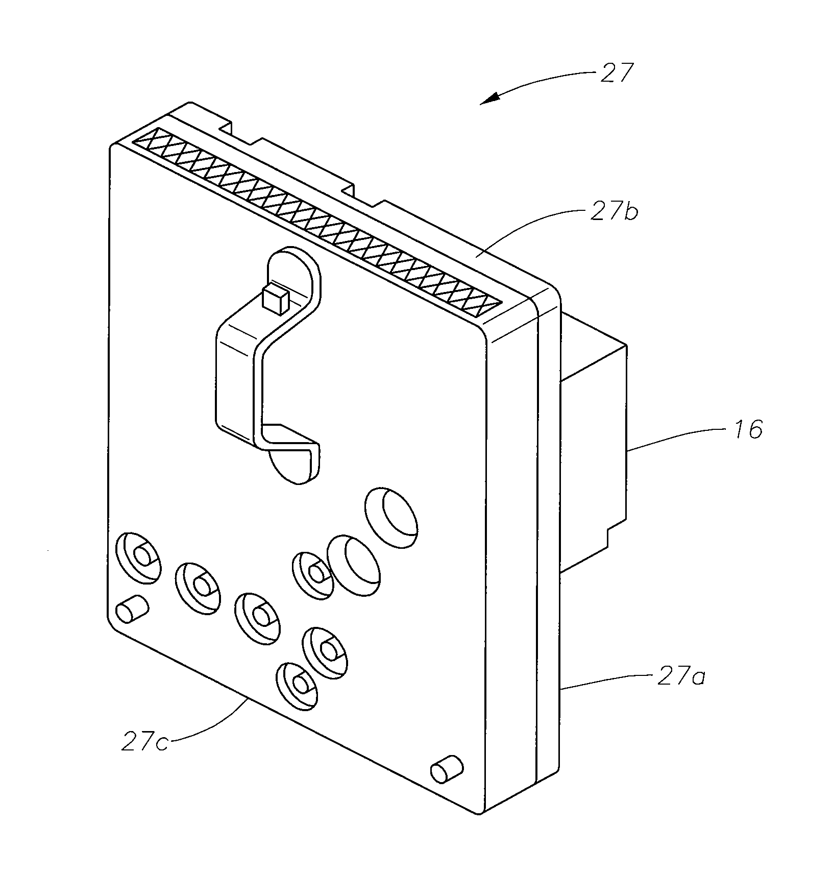
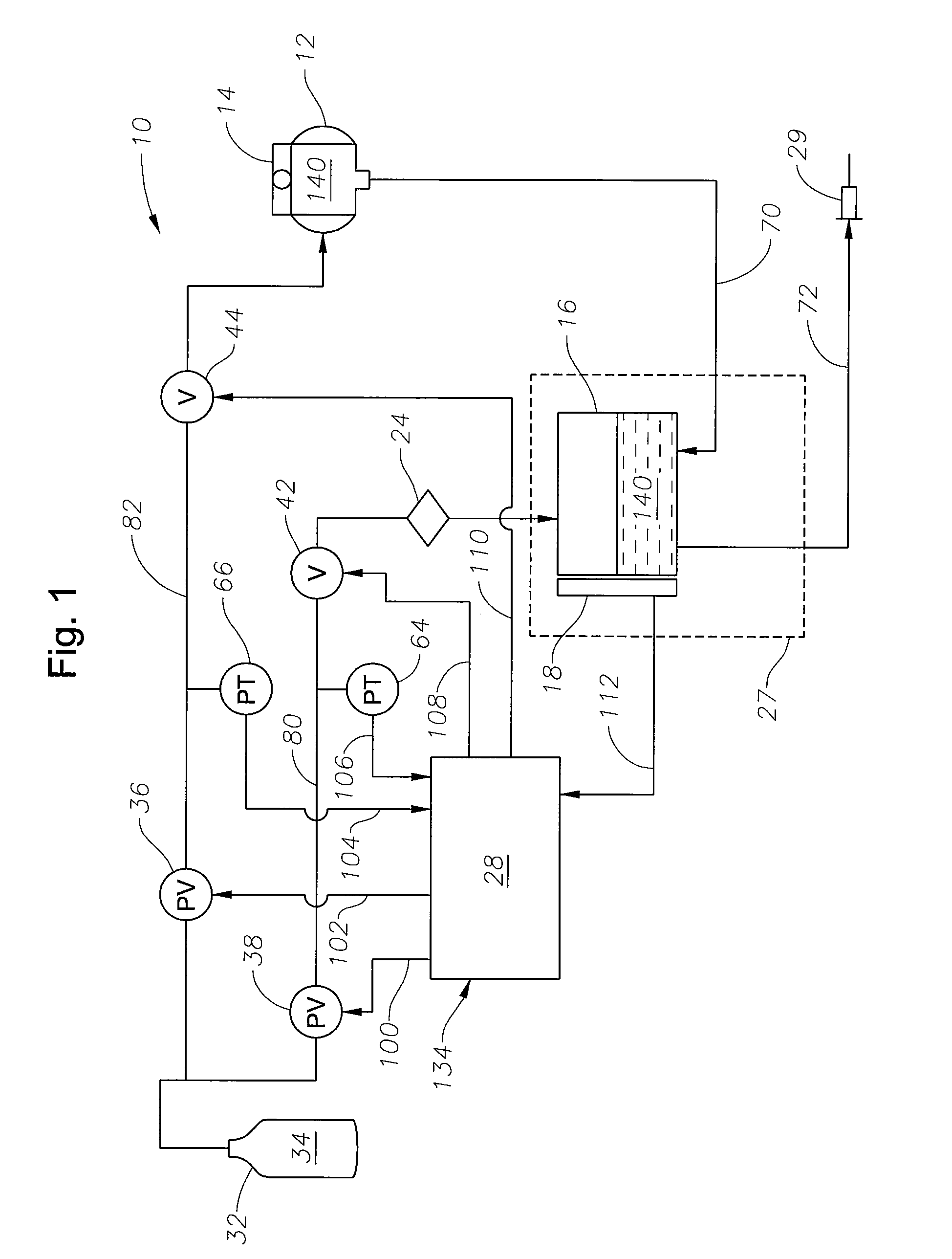
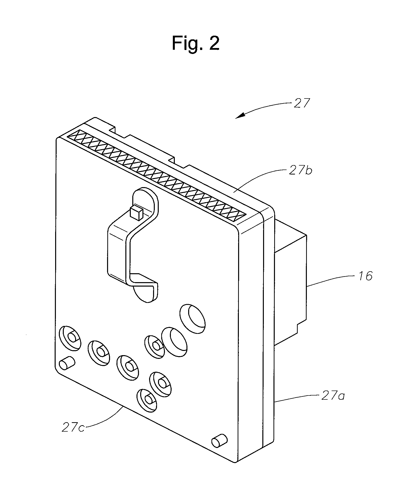
[0011]The preferred embodiments of the present invention and their advantages are best understood by referring to FIGS. 1-3 of the drawings, like numerals being used for like and corresponding parts of the various drawings. As shown in FIG. 1, ophthalmic microsurgical system 10 includes a pressure cuff 12, an infusion source 14, an infusion chamber 16, fluid level sensor 18, a filter 24, a surgical device 29, a computer or microprocessor 28, a receiver 32, proportional solenoid valves 36 and 38, “on / off” solenoid valves 42 and 44, and pressure transducers 64 and 66. Receiver 32 contains a pressurized gas 34, preferably air. Infusion chamber 16, fluid level sensor 18; portions of infusion fluid lines 70 and 72, and portions of a gas line 80 are preferably disposed in a surgical cassette 27. Infusion source 14, infusion chamber 16, and surgical device 29 are fluidly coupled via infusion fluid lines 70 and 72. Infusion source 14, infusion chamber 16, filter 24, and receiver 32 are flui...


PUM


Abstract

An improved method for controlling intraocular pressure during ophthalmic surgery.

Description

[0001]This application claims the priority of U.S. Provisional Application Ser. No. 60 / 847,438 filed on Sep. 27, 2006.FIELD OF THE INVENTION[0002]The present invention generally pertains to microsurgical systems and more particularly to controlling intraocular pressure in ophthalmic surgery.DESCRIPTION OF THE RELATED ART[0003]During small incision surgery, and particularly during ophthalmic surgery, small probes are inserted into the operative site to cut, remove, or otherwise manipulate tissue. During these surgical procedures, fluid is typically infused into the eye, and the infusion fluid and tissue are aspirated from the surgical site.[0004]Maintaining an optimum intraocular pressure during ophthalmic surgery is currently problematic. When no aspiration is occurring, the pressure in the eye becomes the pressure of the fluid being infused into the eye. This pressure is typically referred to as the “dead head pressure”. However, when aspiration is applied, the intraocular pressure...

Claims


Application Information

Patent Timeline
Patent Type & Authority Applications(United States)
IPC IPC(8): A61B18/04A61B5/00
CPCA61B3/16A61F9/00736A61M3/0216A61M2205/12A61M2210/0612A61M3/0237A61M3/0201
Inventor GAO, SHAWN X.HOPKINS, MARK A.WILLIAMS, DAVID L.
Owner ALCON INC
Why Eureka
Try Eureka