Portable pneumatic washing device

a portable, washing device technology, applied in the direction of transportation and packaging, physical therapy, packaging, etc., can solve the problems of inability to apply, inconvenient operation, and inability to design and manufacture electric washing devices,

Inactive Publication Date: 2008-04-03
LAI SHIN BING
View PDF6 Cites 10 Cited by
  • Summary
  • Abstract
  • Description
  • Claims
  • Application Information

AI Technical Summary

Benefits of technology

[0011]a control valve 4 installed to the distal portion of said body 1, a handle 41 outside the body 1 switches on / off the inlet orifice 141 inside said valve pipe 14.

Problems solved by technology

Such a fixed and, of course, electrified washing device is not designed as personal belongings, which could not be applied to one at one's will wherever he goes.
A number of steps are requested to fulfill the demands of the washing device to release a spring 41 press the liner to jet out water, not only the flow rate of the jet is out of control, but also the washing duration is unpredictable.
Where the middle portion is bent the fluid may be blocked, after a longer while, the bent hose may be damaged that make a crack visible to leak out the fluid from rough usage.
Although a battery chamber 11 is situated on the top portion inside the cylinder, but moisture of leaking out water may result in short circuit in between.
Furthermore, the hermetically sealed motor 2, when breaking down, may lose the motive force, then the water is no longer jetted out.
It may cause inconvenience to the people suffered from such as hemorrhoids as they depart for anywhere away from their homes.

Method used


Image

  • Portable pneumatic washing device
  • Portable pneumatic washing device
  • Portable pneumatic washing device

Examples


first embodiment

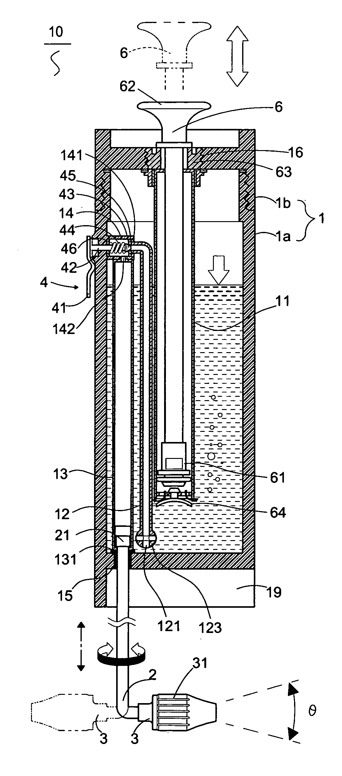
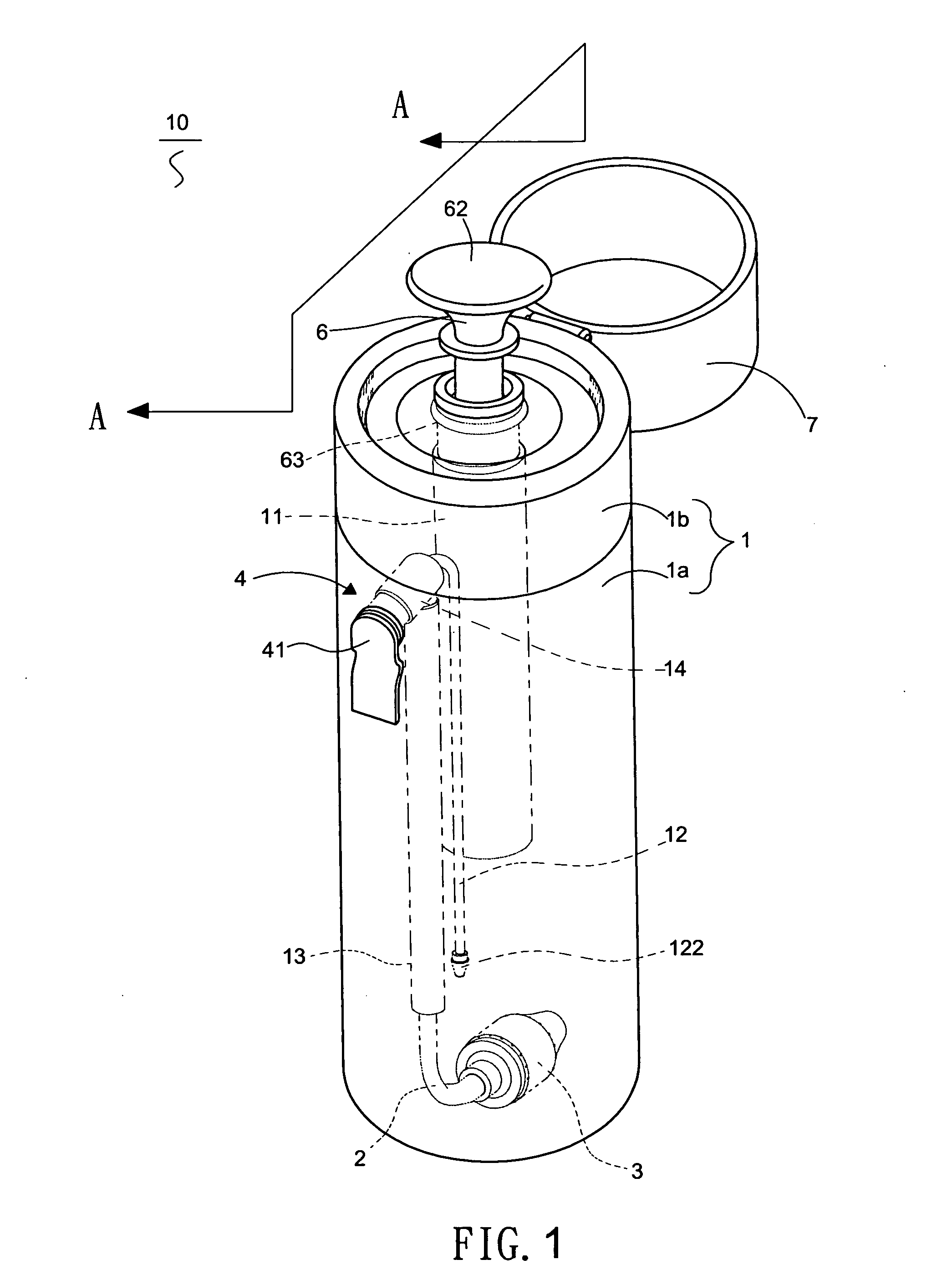
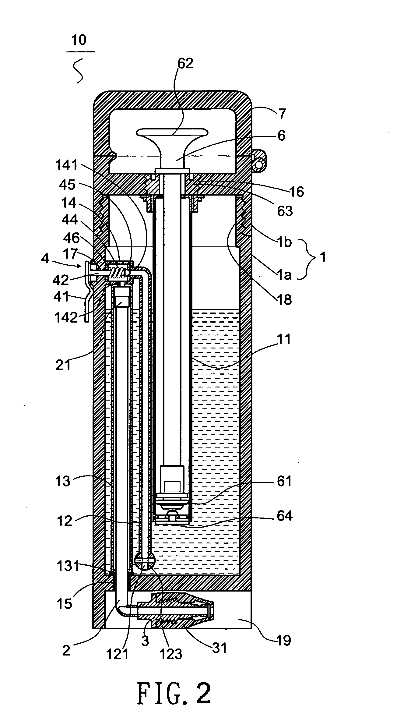
[0024]Refer to FIGS. 1 and 2, a perspective view of the pneumatic washing device of the first embodiment of the present invention, a cross sectional view indicated by A-A in FIG. 1 are illustrated. A pneumatic washing device 10 includes a body 1, a spray pipe 2, a spray head 3, a control valve 4, a push rod 6 and a cover 7. Said body 1 is a container with internal circular diameter filled with liquid, the body 1 can be integrally formed by injection modeling. Or the body 1 is assembled by a base cylinder 1a and a screw top cover 1b threaded to an opening at a distal end of the base cylinder 1a. When water supply is about to re-fill, only the screw top cover 1b is screwed open to fill the liquid within. Next, a water supply orifice (not shown) can be formed through the cover 1b or a sidewall with a water supply cover (not shown) threaded to the water supply orifice, where the water supply cover is screwed open, the liquid can be re-filled within the body 1.

[0025]Inside said body 1, a...

second embodiment

[0035]Refer to FIG. 5, a perspective view of the pneumatic washing device of the second embodiment of the present invention is illustrated. Refer to FIG. 6, an assembled view of the pneumatic washing device of FIG. 5 is illustrated.

[0036]In FIGS. 5, 6, the body 1 of the pneumatic washing device having an internal oval diameter, where the first pipe 11 and push rod 6 are located at one side of the body 1, and a water supply orifice 16 as well as a cover 5 are located at the other side of the body 1.

[0037]Furthermore, the body 1 of the second embodiment is not composed of a base cylinder 1a and a cover 1b as described in the first embodiment. But a water supply orifice 16 and a water supply cover 5 are located at the distal end of the body 1. Users only need to take off the water supply cover 5, liquid can be filled into the body 1. Besides, a slot 71 formed through the cover 7 is suitable for a cord (not shown) passing therethrough to facilitate bringing the washing device out or han...


PUM


Abstract

Portable pneumatic washing device 10 having a body 1 consists of three axially arrayed pipes 11˜13, a transversal valve pipe 14. Pipe 11 impelled by a push rod 6 to pump air into body 1. Distal ends of pipes 12,13 connected to inlet, outlet orifices of the valve pipe 14 respectively. But a proximal end of the pipe 13 securely connected to a hole 15 at a proximal end of the body 1. A control valve 4 installed outside the sidewall of the body 1 switches on/off the inlet orifice 141 of the valve pipe 14. When the inlet orifice 141 open, a liquid retained in the body 1 flows through pipe 12, valve pipe 14 into a telescopic spray pipe 2 of the pipe 13 to spill liquid from the spray head 3 at a distal end of the spray pipe 2 outside the hole 15.

Description

FIELD OF THE INVENTION[0001]The present invention relates to a pneumatic washing device, particularly to a portable timely releasing liquid to wash an excretory organ of human kind or a dead space of stool.BACKGROUND OF THE INVENTION[0002]Nowadays, an improved living standard is commending whatever sanitary problems encountered by the people suffered from such as hemorrhoids (piles) must be provided with personal solution to the problems. Therefore, kinds of stools with hemorrhoids-free function are already promoted on the market. But, a washing device is fixed inside the stool, which must be equipped with an electric circuit panel and electrified to operate in use. Such a fixed and, of course, electrified washing device is not designed as personal belongings, which could not be applied to one at one's will wherever he goes. In consideration of the problems encountered by the people suffered from hemorrhoids, especially for women, disabled, obesity etc., those skilled in the art hav...

Claims


Application Information

Patent Timeline
Patent Type & Authority Applications(United States)
IPC IPC(8): B05B9/04B65D83/00A47K3/26
CPCB05B9/0413A47K7/08
Inventor LAI, SHIN-BING
Owner LAI SHIN BING
Why Eureka
Try Eureka