Controlling filter in connection with cyclic transmission format

a control filter and transmission format technology, applied in the field of transmission signal blocks in a cyclic transmission format, can solve the problems of inability to accurately time out transmissions

Inactive Publication Date: 2008-04-03
NOKIA CORP
View PDF3 Cites 43 Cited by
  • Summary
  • Abstract
  • Description
  • Claims
  • Application Information

AI Technical Summary

Benefits of technology

[0019]FIG. 4 illustrates a frequency response of a root raised cosine filter,

Problems solved by technology

Thus, accurate timing of transmissions is not possible.
For example, when user equipment is accessing a network for the first time, it is unaware of correct timing offset used to combat propagation delay.
In addition, the timing offset of user equipment may be out of date if the user equipment has not been transmitting for a long time.
In many cases, the delay uncertainty of the asynchronous transmission is very large compared with the width of the cyclic prefix that is sufficient for synchronous transmission.
Transmissions on adjacent frequency bands usually interfere with each other.
Asynchronous transmissions produce large interference to the user equipment in adjacent channels within the system bandwidth.
On the other hand, if the roll-off is optimized without taking into account the asynchronous transmission, performance of the synchronous transmission is varying in an unpredictable way depending on the presence of the asynchronous transmission on an adjacent frequency resource.

Method used


Image

  • Controlling filter in connection with cyclic transmission format
  • Controlling filter in connection with cyclic transmission format
  • Controlling filter in connection with cyclic transmission format

Examples


Embodiment Construction

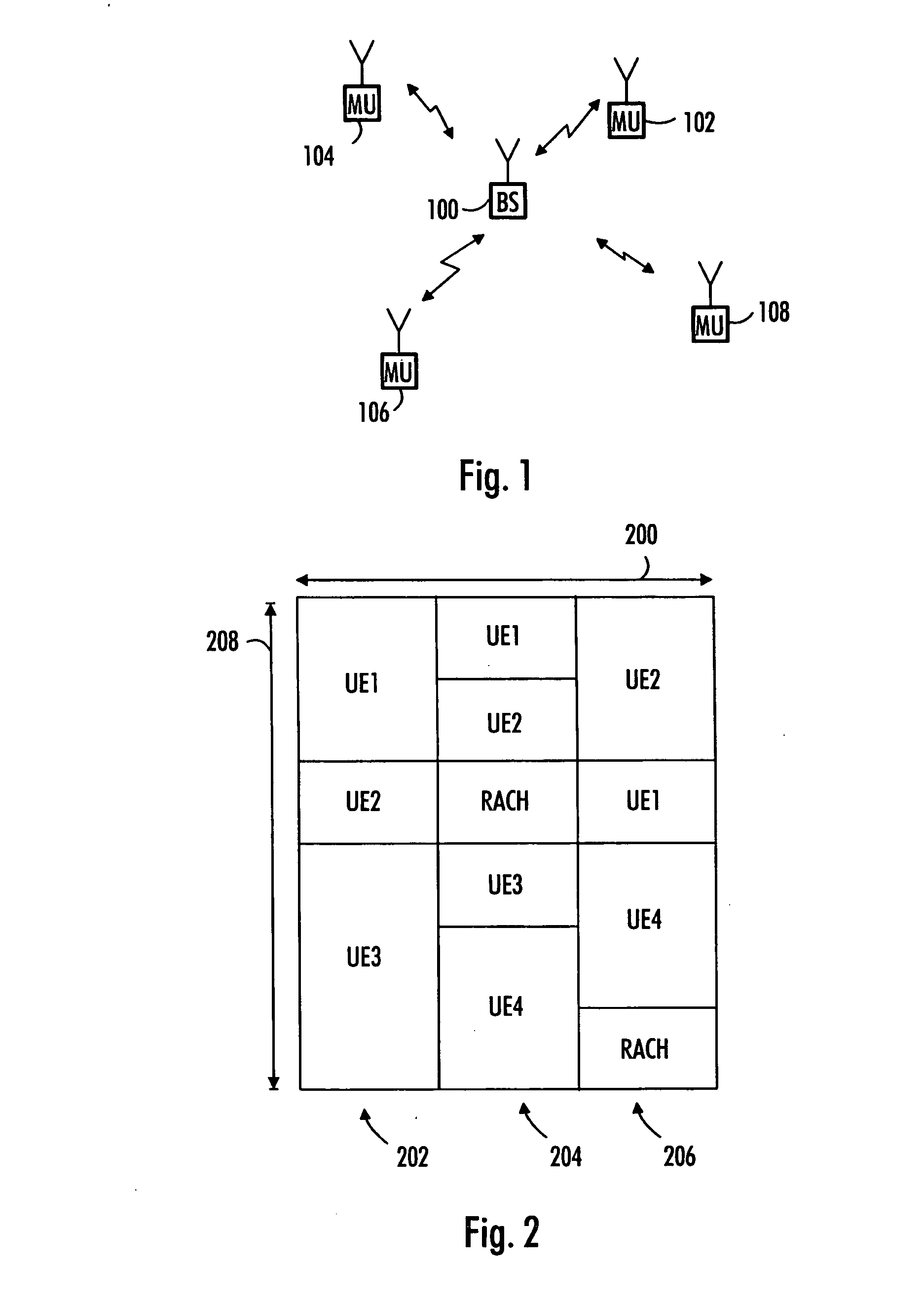
[0026]With reference to FIG. 1, examine an example of a data transmission system in which embodiments of the invention may be applied. The present invention is applicable in various telecommunication systems where different multiple access methods may be used. A typical example of a system in which the invention may be applied is the evolution of the third generation system utilizing EUTRA (Enhanced Universal Terrestrial Radio Access) as a radio access network. EUTRA is currently being developed. However, the embodiments of the invention are not limited to EUTRA.

[0027]FIG. 1 shows a base station 100 and a group of mobile units 102, 104, 106 and 108. In this example, the mobile units 102-108 communicate in uplink direction with the base station 100 using SC-FDMA (Single Carrier Frequency Division Multiple Access) multiple access scheme. In this example, uplink radio resources are divided in time sub-frames and frequency blocks. These resource units of frequency and time are allocated...


PUM


Abstract

A method for controlling a filter, a transmitter, a receiver and an apparatus are provided. The apparatus comprises a filter configured to filter signal blocks to be transmitted in a cyclic transmission form and a controller configured to select a roll-off factor of the filter for a signal block depending on whether transmission is performed in a synchronous or an asynchronous mode.

Description

FIELD [0001]The invention relates to transmitting signal blocks in a cyclic transmission format.BACKGROUND[0002]In many communication systems, both synchronous and asynchronous transmission modes are used. In the synchronous transmission mode, a transmitter and a receiver are synchronized with each other. In such cases, the receiver may control the transmission timing of the transmitter, for example. In the asynchronous transmission mode, there is no common clock between a transmitter and receiver. Thus, accurate timing of transmissions is not possible.[0003]In several systems, transmission is performed block-wise. Thus, symbols to be transmitted are grouped into blocks of a given size prior to transmission. Furthermore, a cyclic transmission mode may be utilized. In a realization of a cyclic transmission mode, each block to be transmitted is made cyclic by inserting a cyclic prefix, for example a copy of the tail part of the block, to the beginning of the block. A cyclic prefix pre...

Claims


Application Information

Patent Timeline
Patent Type & Authority Applications(United States)
IPC IPC(8): H04K1/10
CPCH04L25/03834H04L27/2626H04L27/2602H04L27/26265
Inventor KORHONEN, JUHA S.PAJUKOSKI, KARITIIROLA, ESAVAISANEN, PETRI J.
Owner NOKIA CORP
Why Eureka
Try Eureka