Domestic Cleaning Appliance

a cleaning appliance and domestic technology, applied in the field of domestic appliances, can solve problems such as user inconvenience and chassis damag

Inactive Publication Date: 2008-04-10
DYSON TECH LTD
View PDF9 Cites 66 Cited by
  • Summary
  • Abstract
  • Description
  • Claims
  • Application Information

AI Technical Summary

Benefits of technology

[0011]The invention is particularly applicable to vacuum cleaners. The invention prevents a user from releasing the separating apparatus comprising a collecting chamber employed for collecting dirt and dust from the chassis when the user is carrying the vacuum cleaner.

Problems solved by technology

A problem which may be encountered with such appliances is that, when the user is carrying the appliance by means of the handle, he may accidentally release the catch holding the collecting chamber to the chassis.
This may cause damage to the chassis as well as being an inconvenience to the user.

Method used


Image

  • Domestic Cleaning Appliance
  • Domestic Cleaning Appliance
  • Domestic Cleaning Appliance

Examples


Embodiment Construction

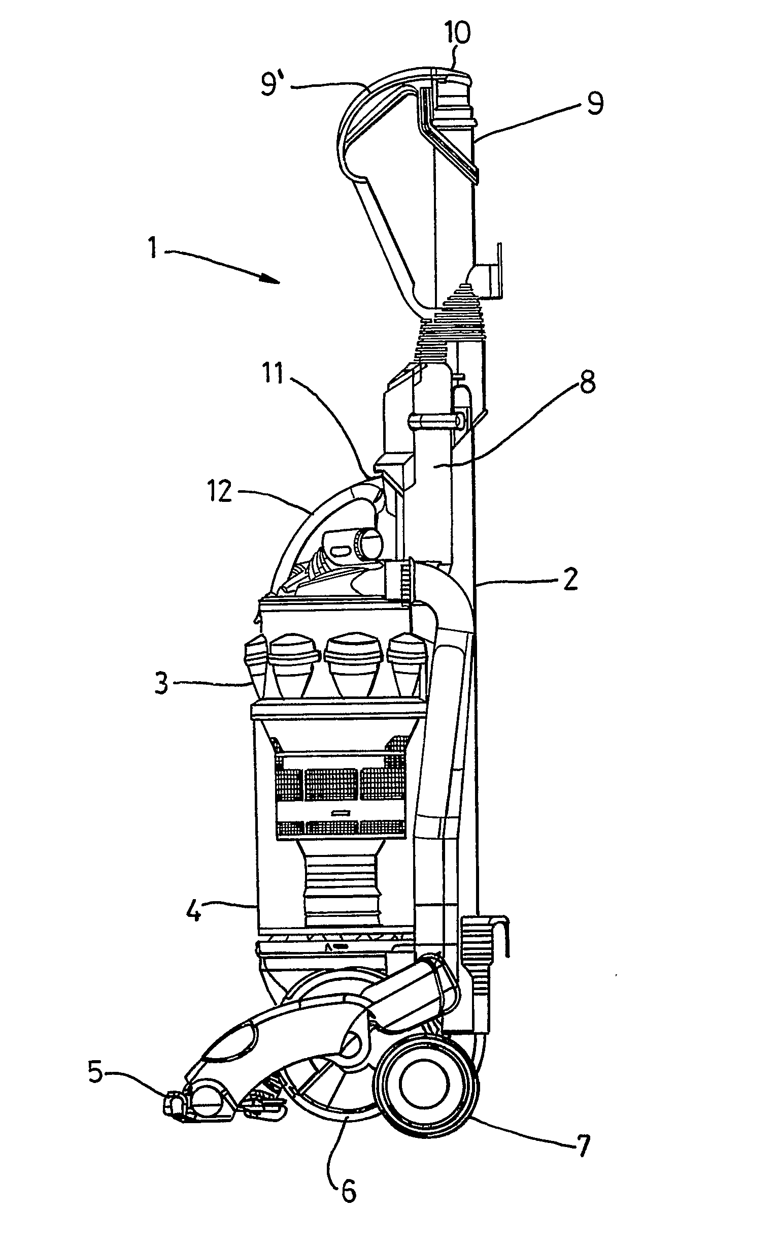
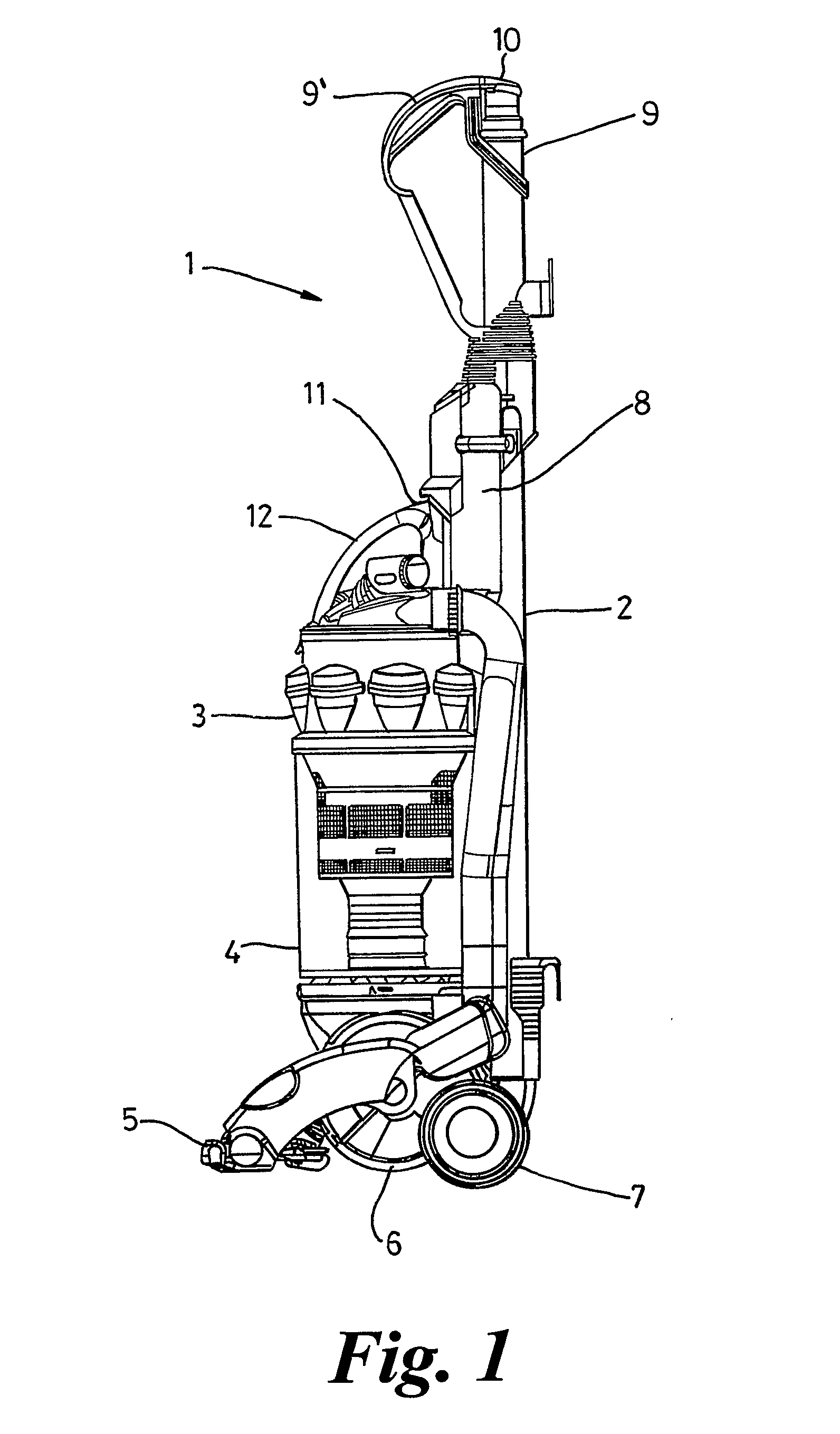
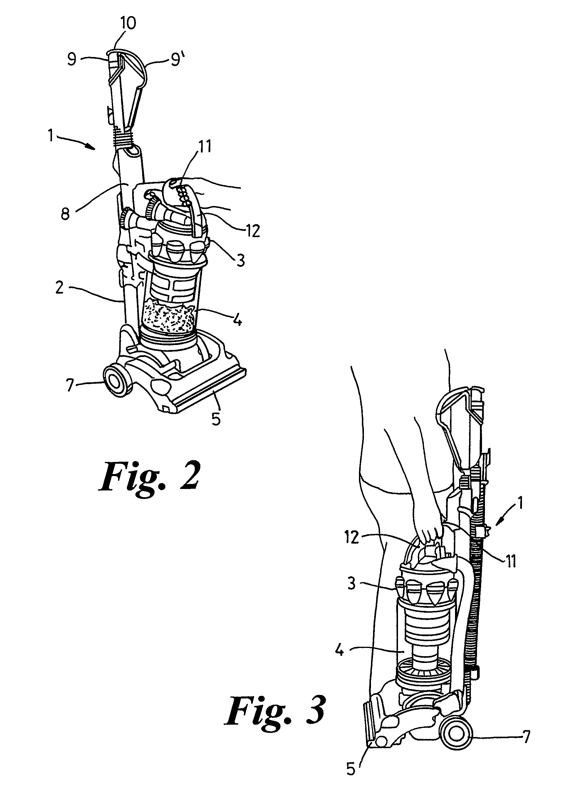
[0025]Referring to FIGS. 1, an upright vacuum cleaner indicated generally by the reference numeral 1 comprises a main chassis 2 which supports dirt and dust separation apparatus 3 incorporating a collecting chamber 4. The lower part of the vacuum cleaner 1 comprises a cleaner head 5 for engaging with the floor surface. The cleaner head 5 has a downwardly facing suction inlet and a brush bar (not shown), mounted in the mouth of the inlet, for agitating the floor surface. The cleaner head 5 is pivotably mounted to a motor housing 6, which houses the motor and fan of the cleaner 1. Support wheels 7 are mounted to either side of the motor housing 6 for supporting the cleaner 1 and allowing movement across a floor surface.

[0026]A spine 8 of the chassis 2 extends upwardly from the motor housing 6 to provide support for the components of the cleaner 1. A cleaning wand 9 having a second dirty air inlet 10 is connected by way of a hose (not shown) to the chassis 2 at the base of the spine 8....


PUM


Abstract

A domestic appliance such as a cyclonic vacuum cleaner includes a component such as separating apparatus, carried by a chassis. A catch is provided and is operable to release the component from the chassis. The component and the chassis are able to move slightly with respect to each other. When the appliance is lifted, lugs on the separating apparatus move into slots on the chassis so as to inhibit release of the catch when the appliance is lifted. Thus, accidental release of the separating apparatus from the chassis is avoided.

Description

REFERENCE TO RELATED APPLICATIONS[0001]This application is a national stage application under 35 USC 371 of International Application No. PCT / GB2005 / 002691, filed Jul. 8, 2005, which claims the priority of United Kingdom Application No. 0416476.0, filed Jul. 23, 2004, the contents of both of which prior applications are incorporated herein by reference.FIELD OF THE INVENTION[0002]The invention relates to a domestic appliance, such as a vacuum cleaner.BACKGROUND OF THE INVENTION[0003]Vacuum cleaners which separate dirt and dust from an airflow without the use of a filter bag, so-called bagless vacuum cleaners, are becoming increasingly popular. Most bagless cleaners use cyclonic or centrifugal separation to spin dirt and dust from the airflow. By avoiding the use of a filter bag as the primary form of separation, it has been found possible to maintain a consistently high level of suction, even as the collecting chamber fills with dirt and dust.[0004]In a typical cyclonic vacuum clean...

Claims


Application Information

Patent Timeline
Patent Type & Authority Applications(United States)
IPC IPC(8): A47L9/16A47L5/00A47L9/10A47L5/28A47L9/32
CPCA47L5/28A47L9/32A47L9/1691A47L9/16A47L9/10
Inventor GENN, STUART LLOYD
Owner DYSON TECH LTD
Why Eureka
Try Eureka