Check valve for vacuum sewage pipe and vacuum sewage system

a technology for vacuum sewage and check valves, which is applied in the direction of valve operating means/release devices, functional valve types, sewage draining, etc., can solve the problems of increasing the cost of installation of the check valve itself and the loss of pipes

Inactive Publication Date: 2008-04-10
EBARA CORP
View PDF14 Cites 25 Cited by
  • Summary
  • Abstract
  • Description
  • Claims
  • Application Information

AI Technical Summary

Problems solved by technology

This is because equal vacuum pressure is developed in all regions of the main pipe including the upstream side of the junction point A. Such a flow toward the upstream side would prevent a smooth flow of the sewage, resulting in an increased loss in the pipes.
However, installation of the check valve itself incurs an increased cost.

Method used


Image

  • Check valve for vacuum sewage pipe and vacuum sewage system
  • Check valve for vacuum sewage pipe and vacuum sewage system
  • Check valve for vacuum sewage pipe and vacuum sewage system

Examples


Embodiment Construction

[0029]Embodiments of the present invention will be described below with reference to the drawings. FIGS. 4 through 6 are external views each showing a check valve for use in a vacuum sewage pipe according to the present invention, and each view illustrates the check valve having no closing mechanism. More specifically, FIG. 4 is a front view, FIG. 5 is a side view, and FIG. 6 is a plan view.

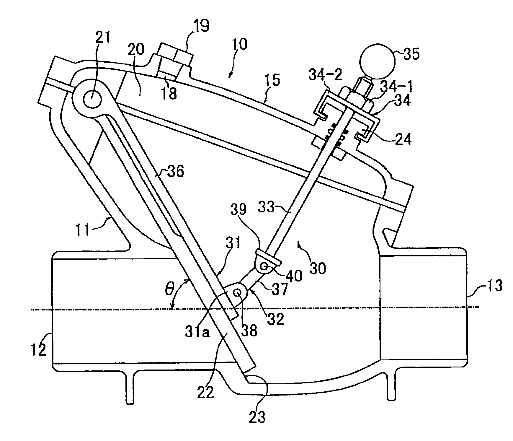
[0030]As shown in FIGS. 4 through 6, the check valve for use in a vacuum sewage pipe comprises a body 11 having a sewage inlet 12 and a sewage outlet 13. The sewage inlet 12 is to be connected to an upstream side of a vacuum sewage pipe (not shown in the drawings), and the sewage outlet 13 is to be connected to a downstream side of the vacuum sewage pipe. Thus, sewage is introduced into the body 11 through the sewage inlet 12, and flows out through the sewage outlet 13 toward the downstream side (i.e., in a direction indicated by arrow E). The sewage is prevented from flowing in the opposite dire...


PUM


Abstract

The present invention provides a check valve for use in a vacuum sewage pipe. The check valve includes a body having a sewage inlet and a sewage outlet to be coupled to the vacuum sewage pipe, a flap valve element disposed in the body and rotatably supported by a shaft, and a closing mechanism. The closing mechanism can keep the flap valve element in a closed state so as to allow the flap valve element to function as a gate valve. The closing mechanism can also limit an opening degree of the flap valve element so as to allow the flap valve element to function as a check valve.

Description

BACKGROUND OF THE INVENTION[0001]1. Field of the Invention[0002]The present invention relates to a check valve to be installed in a vacuum sewage pipe providing fluid communication between a source of sewage and a vacuum station of a vacuum sewage collection system, and also relates to a vacuum sewage system having a vacuum sewage pipe provided with such a check valve.[0003]2. Description of the Related Art[0004]FIG. 1 is a schematic view showing an example of a vacuum sewage system. As shown in this drawing, sewage, discharged from houses 100, factories, and the like, flows through gravity-flow-type inlet pipes 101 into vacuum valve units 102 which are buried underground. Each of the vacuum valve units 102 has a vacuum valve 103 operable to be opened when an amount of sewage stored therein reaches a predetermined value. Once the vacuum valve 103 is opened, the sewage is sucked via a vacuum sewage pipe 1, so that the sewage is collected in a sewage collection tank 105 of a vacuum st...

Claims


Application Information

Patent Timeline
Patent Type & Authority Applications(United States)
IPC IPC(8): F16K15/03
CPCE03F1/006E03F1/007F16K1/2007F16K1/523F16K15/03E03F7/04Y10T137/7732Y10T137/79Y10T137/7898Y10T137/7903
Inventor SHIMIZU, OSAMUHIROTO, YUJIIKEDA, KEISUKEOGAKI, FUYUKI
Owner EBARA CORP
Why Eureka
Try Eureka